Nissan Juke Service and Repair Manual : Structure and operation
Sectional View
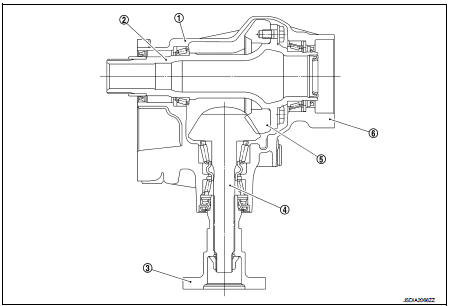
1. Transfer cover
2. Ring gear shaft
3. Companion flange
4. Drive pinion
5. Ring gear
6. Transfer case
Operation Principle
POWER TRANSFER DIAGRAM
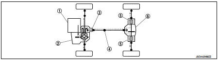
1. Engine
2. Transaxle
3. Transfer
4. Propeller shaft
5. Electric controlled coupling
6. Rear final drive
ELECTRIC CONTROLLED COUPLING
1. The 4WD control module supplies command current to each electric controlled coupling (4WD solenoid).
2. Each of control clutch is engaged by electromagnet and torque is detected in control clutch.
3. The cam operates in response to control clutch torque and applies pressure to main clutch.
4. Each of main clutch transmits torque to right and left rear wheels according to pressing power.
NOTE
:
Change each pressing power according to 4WD mode atatus
and cornering conditions
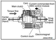
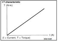
• Transmission torque to the right and left rear wheels is determined according to command current.
 Component parts
Component Parts Location
LHD models
1. ABS actuator and electric unit (control
unit)
Refer to BRC-97, "Component Parts
Location".
2. ECM
Refer to EC-25, "ENGINE CONTROL
SYSTEM ...
 System
4WD system : System Diagram
INPUT/OUTPUT SIGNAL
It transmits/receives each signal from the following 4WD control module via
CAN communication line.
4WD system : System Description
• 4WD mo ...
Other materials:
P1226 TP sensor
DTC Logic
DTC DETECTION LOGIC
DTC CONFIRMATION PROCEDURE
1.PRECONDITIONING
If DTC Confirmation Procedure has been previously conducted, always perform
the following procedure
before conducting the next test.
1. Turn ignition switch OFF and wait at least 10 seconds.
2. Turn ignition swit ...
Connector information
How to Read Connector Type
1 : Connector model
2 : Cavity
3 : Male (M) and female (F) terminals
4 : Connector color
5 : Special type
B Body Harness
D Door Harness
E Engine Room Harness
F Engine Control Harness
M Ma ...
Headlamp washer nozzle and tube
Exploded View
1. Washer tank
2. Headlamp washer tube (tank side)
3. Headlamp washer tube RH
4. Headlamp washer nozzle connector
RH
5. Headlamp washer nozzle bracket RH
6. Headlamp washer nozzle RH
7. Headlamp washer nozzle joint
8. Headlamp washer nozzle bracket LH
9. Headlamp washe ...
