Nissan Juke Service and Repair Manual : System
4WD system : System Diagram
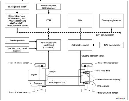
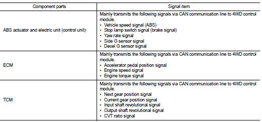
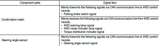
INPUT/OUTPUT SIGNAL
It transmits/receives each signal from the following 4WD control module via CAN communication line.
4WD system : System Description
• 4WD mode is selectable among 2WD, 4WD-V, and 4WD by operating the 4WD mode switch.
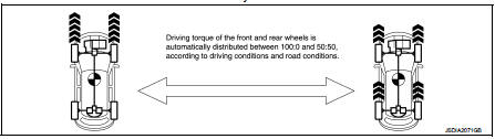
• When judging driving conditions and road surface conditions based on signals transmitted from each sensor and switch, the 4WD system automatically controls torque distribution of front and rear wheels and both rear wheels, depending on the situation.
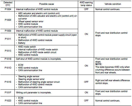
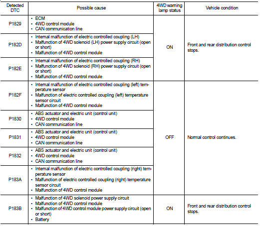
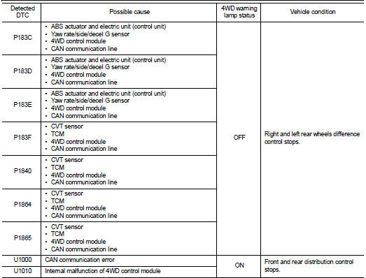
• In accordance with fail-safe function, when system is malfunctioning, 4WD control stops, and the system becomes rear wheel drive. Refer to DLN-19, "4WD SYSTEM : Fail-safe".
• When a high load status continues for electric controlled coupling, 4WD control temporarily becomes rear wheel drive, according to protection function. Refer to DLN-21, "4WD SYSTEM : Protection Function".
4WD system : Torque Split Control
2WD mode
• Vehicle is in front-wheel drive.
4WD-V mode
Normal Control
• Pressing force of multiple disc clutch is controlled by electric control.
Driving torque distribution of front and
rear wheels changes automatically between approximately 100 : 0 (Front wheel
drive) and 50 : 50 (4WD) to
have an optimized torque distribution adapted to road condition change.
• When spin occurs on front wheel, distribute optimum torque to rear wheel and keep stable driving.
• On roads which do not require 4WD, it contributes to improved fuel economy by driving in conditions close to front-wheel drive and it results in better fuel efficiency.
Cornering Control
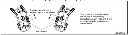
• Torque between both rear wheels is automatically changed between 100 : 0 and 0
: 100 for distributing optimum
torque that depends on the driving conditions and road surface conditions.
• Producing a difference between both rear wheels enables sporty and smooth handling.
• The vehicle cornering status is judged according to information from each sensor, and the optimum torque is distributed to rear wheels for preventing tight cornering/braking symptom.
4WD mode
• The 4WD mode controls torque for obtaining suitable torque for driving on
slippery roads (e.g. snow-covered
roads) and provides more stable driving, compared to 4WD-V.
4WD system : Fail-safe
When a system malfunction occurs, the 4WD warning lamp turns ON and the 4WD control becomes 2WD state.
4WD system : Protection Function
4WD system activates its protection function (shuts down 4WD system temporarily) if 4WD system detects high load continuously, the front wheel tire size differs from the rear tire size or the rear RH wheel tire size differs from the rear LH tire size. (4WD system is automatically restored if 4WD system no longer detects any overload or the tire size difference is eliminated.)
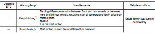
*1: 2 times/second (blinking for approximately 1 minute and then turned
OFF)
*2: 1 time/2 seconds (continuing to blink until ignition switch is turned OFF)
NOTE
:
• If the warning lamp blinks slowly during driving but remains OFF after the
engine is restarted, the system is
normal. If it again blinks slowly after driving for some time, vehicle must be
inspected.
• When there is a difference of revolution speed between the front and rear wheel the shift occasionally changes to direct 4-wheel driving conditions automatically. This is not a malfunction.
 Structure and operation
Sectional View
1. Transfer cover
2. Ring gear shaft
3. Companion flange
4. Drive pinion
5. Ring gear
6. Transfer case
Operation Principle
POWER TRANSFER DIAGRAM
1. Engine
2. Transax ...
 Diagnosis system (4WD control module)
CONSULT-III Function
APPLICATION ITEMS
CONSULT-III can display each diagnostic item using the diagnostic test modes
as follows.
*: The following diagnosis information is erased by erasing.
• ...
Other materials:
Hazard warning flasher switch
Push the switch on to warn other drivers when you must stop or park under emergency
conditions.
All turn signal lights will flash.
WARNING
• If stopping for an emergency, be sure to move the vehicle well off
the road.
• Do not use the hazard warning flashers while moving on the ...
Symptom diagnosis
Squeak and rattle trouble diagnoses
Work Flow
CUSTOMER INTERVIEW
Interview the customer if possible, to determine the conditions that exist
when the noise occurs. Use the Diagnostic
Worksheet during the interview to document the facts and conditions when the
noise occurs and any of
the cu ...
Basic inspection
DIAGNOSIS AND REPAIR WORKFLOW
Work Flow
OVERALL SEQUENCE
DETAILED FLOW
1.INTERVIEW FOR MALFUNCTION
Interview the symptom to the customer.
>> GO TO 2.
2.SYMPTOM CHECK
Check the symptom from the customer's information.
>> GO TO 3.
3.BASIC INSPECTION
Check the operation o ...
