Nissan Juke Service and Repair Manual : Component parts
Component Parts Location
LHD models
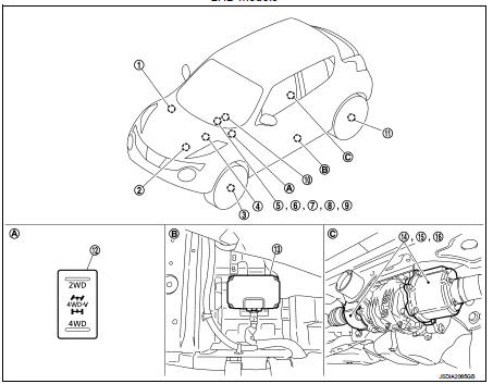
1. ABS actuator and electric unit (control unit) Refer to BRC-97, "Component Parts Location".
2. ECM Refer to EC-25, "ENGINE CONTROL SYSTEM : Component Parts Location".
3. Front wheel sensor Refer to BRC-97, "Component Parts Location".
4. TCM Refer to TM-131, "CVT CONTROL SYSTEM : Component Parts Location".
5. Combination meter Refer to MWI-4, "METER SYSTEM : Component Parts Location".
6. 4WD warning lamp
(In combination meter)
7 4WD mode indicator lamp (4WD-V)
(In combination meter)
8. 4WD mode indicator lamp (4WD)
(In combination meter)
9. Torque distribution indicator
(In combination meter)
10. Steering angle sensor
Refer to BRC-97, "Component Parts
Location".
11. Rear wheel sensor Refer to BRC-97, "Component Parts Location".
12. 4WD mode switch
13. 4WD control module 14. 4WD solenoid
(Inside rear final drive)
15. Electric controlled coupling
(Inside rear final drive)
16. Electric controlled coupling temperature
sensor
(Inside rear final drive)
A. Instrument driver lower panel B. Under front (left side) seat C Rear final drive assembly
RHD models
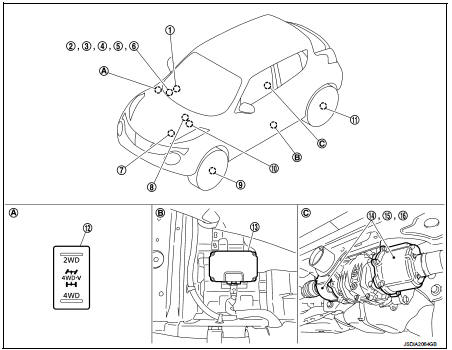
1. Steering angle sensor Refer to BRC-97, "Component Parts Location".
2. Combination meter Refer to MWI-4, "METER SYSTEM : Component Parts Location".
3. 4WD warning lamp
(In combination meter)
4. 4WD mode indicator lamp (4WD-V)
(In combination meter)
5. 4WD mode indicator lamp (4WD)
(In combination meter)
6. Torque distribution indicator
(In combination meter)
7 ECM
Refer to EC-25, "ENGINE CONTROL
SYSTEM :
Component Parts Location".
8. ABS actuator and electric unit (control unit) Refer to BRC-97, "Component Parts Location".
9. Front wheel sensor Refer to BRC-97, "Component Parts Location".
10. TCM Refer to TM-131, "CVT CONTROL SYSTEM : Component Parts Location".
11. Rear wheel sensor Refer to BRC-97, "Component Parts Location".
12. 4WD mode switch
13. 4WD control module 14. 4WD solenoid
(Inside rear final drive)
15. Electric controlled coupling
(Inside rear final drive)
16. Electric controlled coupling temperature
sensor
(Inside rear final drive)
A. Instrument driver lower panel B. Under front (left side) seat C Rear final drive assem
Component Description
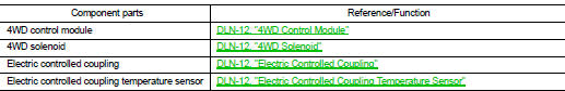
4WD Control Module
• 4WD control module controls driving force distribution by signals from each sensor from front wheel driving mode (100:0) to 4-wheel driving mode (50:50).
• Driving torque between both rear wheels is automatically controlled between 100:0 and 0:100 during acceleration and cornering.
• Front wheel driving conditions is available by fail-safe function if malfunction is detected in 4WD system.
• 4WD actuator relay is integrated with 4WD control module, and supplies 4WD solenoid with voltage.
• Self-diagnosis can be done with CONSULT-III.
4WD Solenoid
4WD solenoid is integrated with each electric controlled coupling, and controls electric controlled couplings by command current from 4WD control module.
Electric Controlled Coupling
Electric controlled couplings are integrated with rear final drive and transmits driving force to rear drive shaft.
For operation, refer to DLN-15, "Operation Principle"
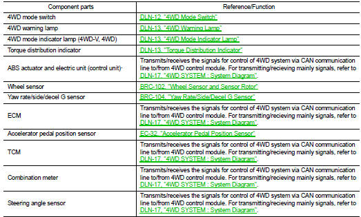
Electric Controlled Coupling Temperature Sensor
• Electric controlled coupling temperature sensor is integrated with each electric controlled coupling.
• Electric controlled coupling temperature sensor detects the electric controlled coupling temperature and transmits a signal to 4WD control module.
4WD Mode Switch
• 4WD mode is selectable among 2WD, 4WD-V, and 4WD by operating the 4WD mode switch while the ignition switch is ON or the engine is running.
• Tilting the switch to the 2WD/4WD side allows mode selection between 2WD and 4WD. To switch mode to 4WD-V, simply position the switch in 4WD-V (neutral position).
4WD Warning Lamp
• After the 4WD system is activated, the 4WD warning lamp turns OFF during front and rear wheels driving torque distribution.
• After the 4WD system is deactivated by fail-safe function and torque distribution of front and rear wheels is stopped, the 4WD warning lamp turns ON to indicate that the state is in 2WD.
NOTE
:
The 4WD warning lamp does not turn ON when only torque distribution of both rear
wheels is stopped by the
fail-safe function.
• The 4WD warning lamp blinks to indicate that the state is in 2WD when the 4WD system is temporarily stopped by the protection function.
• Also turns ON when ignition switch is turned ON, for the purpose of lamp check. Turns OFF after the engine starts if system is normal.
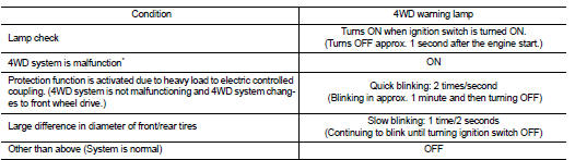
*: The 4WD warning lamp does not turn ON when only torque distribution of both rear wheels is stopped.
NOTE
:
4WD warning lamp also turns ON due to data reception error, CAN communication
error etc.
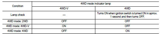
4WD Mode Indicator Lamp
The following is the indications of 4WD mode indicator lamp.
Torque Distribution Indicator
• Torque distribution indicator is displayed when the ODO/TRIP indication on the combination meter is switched.
• The number of bars shows driving force distributed to each tire. (Maximum bars: 3)
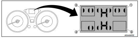
1. Front right side driving torque 2. Front left side driving torque 3. Rear right side driving torque 4. Rear left side driving torque
NOTE
:
The driving force distribution may not match actual one. This is not a system
malfunction.

 Structure and operation
Sectional View
1. Transfer cover
2. Ring gear shaft
3. Companion flange
4. Drive pinion
5. Ring gear
6. Transfer case
Operation Principle
POWER TRANSFER DIAGRAM
1. Engine
2. Transax ...
Other materials:
Precaution for Supplemental Restraint System (SRS) "AIR BAG" and "SEAT BELT
PRE-TENSIONER"
The Supplemental Restraint System such as “AIR BAG” and “SEAT BELT PRE-TENSIONER”,
used along
with a front seat belt, helps to reduce the risk or severity of injury to the
driver and front passenger for certain
types of collision. Information necessary to service the system safely is
include ...
Horn function
Component Function Check
1.CHECK FUNCTION 1
1. Disconnect vehicle security horn relay.
2. Perform “VEHICLE SECURITY HORN” in “ACTIVE TEST” mode of “THEFT ALM” of “BCM”
using CONSULT-
III.
3. Check the horn operation.
Is the operation normal?
YES >> GO TO 2.
NO >> Go to SE ...
Thermostat
Exploded View
1. Radiator hose (upper)
2. Water inlet
3. Rubber ring
4. Thermostat
A. To radiator
: Always replace after every
disassembly.
: N·m (kg-m, ft-lb)
Removal and Installation
REMOVAL
1. Drain engine coolant from radiator. Refer to CO-37, "Draining".
CAUTION:
P ...
