Nissan Juke Service and Repair Manual : MR16DDT : Removal and Installation
REMOVAL
1. Disconnect the battery cable from the negative terminal. Refer to PG-124, "Removal and Installation".
2. Drain engine coolant from radiator. Refer to CO-11, "Draining".
3. Remove charge air cooler. Refer to EM-31, "Removal and Installation".
4. Remove CVT water hose A on thermostat housing side (CVT models). Refer to CO-17, "Exploded View".
5. Remove radiator hose (lower) on thermostat housing side. Refer to CO-17, "Removal and Installation".
6. Move CVT water hose A and radiator hose (lower) to a location where they do not inhibit work.
7. Open “B” terminal cover, in the direction indicated by an arrow, as shown in the figure.
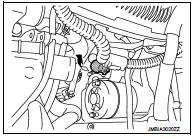
8. Remove “B” terminal nut and “B” terminal harness.
9. Remove “S” terminal nut and “S” terminal harness.
10. Disconnect harness connector (1) from crankshaft position sensor.
11. Remove harness fixing clip (A) from oil pan (upper), and then move harness (2) to a location where they do not inhibit work.
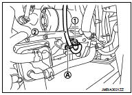
12. Remove starter motor mounting bolts.
13. Remove starter motor forward from the vehicle.
INSTALLATION
Note the following items, and install in the reverse order of removal.
CAUTION:
• Be careful to tighten “B” terminal nut to the specified torque.
• After work is complete fill engine coolant. Refer to CO-12, "Refilling".
 MR16DDT : Exploded View
REMOVAL
1. “S” terminal harness
2. “B” terminal harness
3. Starter motor
4. Cylinder block
: Vehicle front
: N·m (kg-m, in-lb)
: N·m (kg-m, ft-lb)
DISASSEMBLY
Type: S114-902
1. Magneti ...
 MR16DDT : Inspection and Adjustment
INSPECTION
Magnetic Switch Check
• Before starting to check, disconnect the battery cable from the negative
terminal.
• Disconnect “M” terminal of starter motor.
1. Continuity test [between “S ...
Other materials:
Engine maintenance (HR16DE)
Drive belt
DRIVE BELT : Checking
• Inspection should be done only when engine is cold or over 30
minutes after the engine is stopped.
1 : Alternator
2 : Water pump
3 : Crankshaft pulley
4 : A/C compressor
5 : Idler pulley
6 : Drive belt
• Visually check belts for wear, damage, and cracks ...
Speed limiter
Speed limiter : System Diagram
Speed limiter : System Description
INPUT/OUTPUT SIGNAL CHART
*: This signal is sent to the ECM through CAN communication line
BASIC SPEED LIMITER SYSTEM
• Speed limiter is a system that enables to restrict the vehicle speed within
the set speed that is sele ...
Power supply and ground circuit
MULTI DISPLAY UNIT
MULTI DISPLAY UNIT : Diagnosis Procedure
1.CHECK FUSES
Check if any of the following fuses are blown:
Is the check result normal?
YES >> GO TO 2.
NO >> Replace fuse with a new one after repairing the applicable circuit.
2.CHECK POWER SUPPLY CIRCUIT
Check ...
