Nissan Juke Service and Repair Manual : Key interlock cable
Exploded View
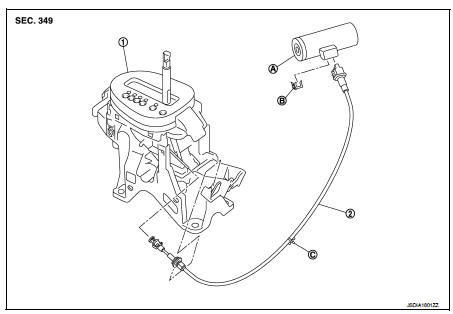
1. CVT shift selector assembly 2. Key interlock cable
A: Key cylinder
B: Clip
C: Clip
Removal and Installation
REMOVAL
CAUTION:
Always apply the parking brake before performing removal and installation.
1. Shift the selector lever to the “P” position.
2. Remove the selector lever knob. Refer to TM-271, "Disassembly and Assembly".
3. Remove the center console. Refer to IP-23, "Removal and Installation".
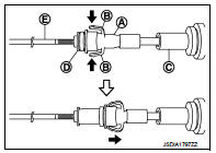
4. Press the pawls (B) of the key interlock cable slider (A) while sliding it in the direction of the casing cap (C), and separate the adjusting holder (D) and slider
E :Key interlock rod
5. Remove the key interlock cable from the CVT shift selector.
6. Remove the steering column lower cover and driver instrument lower panel. Refer to IP-13, "Removal and Installation".
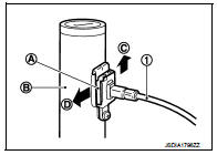
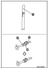
7. Lift clip (A) in the direction of the arrow (
 C) and remove in the
direction of the arrow (  D).
D).
1 :Key interlock cable B :Key cylinder
8. Disconnect the key interlock cable from the key cylinder.
9. Disengage the clip and disconnect the key interlock cable from the vehicle
INSTALLATION
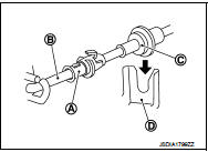
• Install the adjusting holder (A) onto the key interlock rod (B), then install the casing cap (C) onto the CVT shift selector cable bracket (D).
CAUTION:
• When installing the key interlock cable, never bend or twist
the cable forcefully.
• After connecting the key interlock cable to the CVT shift selector cable bracket, be sure to check that the casing cap is completely fastened to the cable bracket. If the casing cap is easily displaced, replace the key interlock cable.
• While pressing the detent rod (B) down, slide the key interlock cable slider (A) toward the key interlock rod (D) side, and install the adjusting holder (C) and key interlock rod.
CAUTION:
• Never squeeze the pawls on the key interlock cable slider
when holding the slider.
• Never apply force in a perpendicular direction to the key interlock rod when sliding the slider.
Inspection
INSPECTION AFTER INSTALLATION
• Check the CVT position. If a malfunction is found, adjust the CVT position. Refer to TM-194, "Inspection and Adjustment".
• The key can be removed only when the selector lever is in the “P” position.
• It must not be possible to turn the ignition switch to LOCK when the selector lever is not in the “P” position.
 Control cable
Exploded View
1. Control cable
2. Lock plate
3. Transaxle assembly
4. Bracket A
5. Bracket B
6. CVT shift selector assembly
A: Manual lever B: Grommet
: N·m (kg-m, ft-lb)
: N·m (kg-m, i ...
 Transmission range switch
Exploded View
1. Transmission range switch
2. Transaxle assem
Removal and Installation
REMOVAL
1. Remove battery. Refer to PG-124, "Removal and Installation".
2. Remove transmission ...
Other materials:
P0131 A/F sensor 1
DTC Logic
DTC DETECTION LOGIC
To judge the malfunction, the diagnosis checks that the A/F signal computed
by ECM from the A/F sensor 1
signal is not inordinately low.
DTC CONFIRMATION PROCEDURE
1.PRECONDITIONING
If DTC Confirmation Procedure has been previously conducted, always turn
ign ...
Fuel filler lid opener
Exploded View
1. Fuel filler lid opener cable
2. Cable protector
3. Fuel filler lid lock assembly
4. Fuel filler lid assembly
5. Spring
6. Bumper rubber
: Clip
: Do not reuse
Fuel filler lid
FUEL FILLER LID : Removal and Installation
REMOVAL
1. Fully open fuel filler lid.
2. Remov ...
Security indicator lamp
Component Function Check
1.CHECK FUNCTION
1. Perform “THEFT IND” in “ACTIVE TEST” mode of “IMMU” of “BCM” using
CONSULT-III.
2. Check security indicator lamp operation.
Is the inspection result normal?
YES >> INSPECTION END
NO >> Go to SEC-159, "Diagnosis Procedure".
...
