Nissan Juke Service and Repair Manual : Control cable
Exploded View
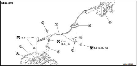
1. Control cable
2. Lock plate
3. Transaxle assembly
4. Bracket A
5. Bracket B
6. CVT shift selector assembly
A: Manual lever B: Grommet
 : N·m (kg-m, ft-lb)
 : N·m (kg-m, in-lb)
Removal and Installation
INSTALLATION
CAUTION:
Always apply the parking brake before performing removal and installation.
1. Remove the battery. Refer to PG-124, "Removal and Installation".
2. Remove the control cable from the CVT shift selector assembly. Refer to TM-270, "Removal and Installation".
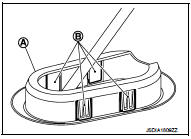
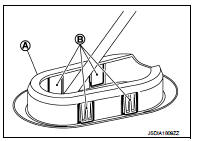
3. Disengage the pawls (B) of the grommet (A), and pull downwards to remove.
4. Remove the control cable installation nut from the manual lever.
5. Remove the lock plate (1).
6. Remove center muffler from the mounting rubber and lower the center muffler downward. Refer to EX-6, "Removal and Installation".
7. Lift up the heat plate.
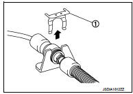
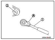
8. Remove the control cable (1) from the bracket (2).
 :Vehicle front
9. Remove the control cable from the vehicle.
10. Remove bracket.
INSTALLATION
Note the following, and install in the reverse order of removal.
• From below the vehicle, press the grommet (A) into place until the pawls (B) make a click sound.
CAUTION:
• Place the grommet on the floor, then fasten it in place from
below the vehicle.
• Check that pulling down on the grommet does not disconnect it.
• Pay attention to the following when connecting the control cable to the CVT shift selector.
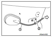
1. When connecting the control cable (1) to the CVT shift selector assembly (2), face the grooved surface of the rib (A) up and insert the control cable until it stops.
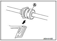
2. Install the socket (A) onto the CVT shift selector.
CAUTION:
• Place the socket onto the CVT shift lever, then fasten it in
place from above.
• Check that the pulling on the socket does not disconnect it.
Inspection
INSPECTION AFTER INSTALLATION
Check the CVT position. If a malfunction is found, adjust the CVT position. Refer to TM-194, "Inspection and Adjustment".
 CVT shift selector
Exploded View
1. Selector lever knob
2. Lock pin
3. Knob cover
4 Position indication panel
5. CVT shift selector assembly
6. CVT shift lock unit
7. Key interlock rod*
8. Indicator lamp
...
 Key interlock cable
Exploded View
1. CVT shift selector assembly
2. Key interlock cable
A: Key cylinder
B: Clip
C: Clip
Removal and Installation
REMOVAL
CAUTION:
Always apply the parking brake before perfor ...
Other materials:
Thermo control amplifier
Component Function Check
1.CHECK A/C ON SIGNAL
With CONSULT-III
1. Turn ignition switch ON.
2. Select “AIR CONDITIONER” of “BCM” using CONSULT-III.
3. Select “THERMO AMP” in “DATA MONITOR” mode, and check status under the
following condition.
Is the inspection result normal?
YES >> ...
Exterior lighting system symptoms
Without daytime running light system
WITHOUT DAYTIME RUNNING LIGHT SYSTEM : Symptom Table
CAUTION:
Perform the self-diagnosis with CONSULT-III before the symptom diagnosis.
Perform the trouble diagnosis
if any DTC is detected.
With daytime running light system
WITH DAYTIME RUNNING LIGHT ...
Precaution
NOTE:
If any malfunction occurs in the RE0F10A model transaxle, replace the entire
transaxle assembly.
• Before connecting or disconnecting the TCM harness connector,
turn ignition switch OFF and disconnect negative battery
cable. Because battery voltage is applied to TCM even if ignition
swi ...
