Nissan Juke Service and Repair Manual : Transmission range switch
Exploded View
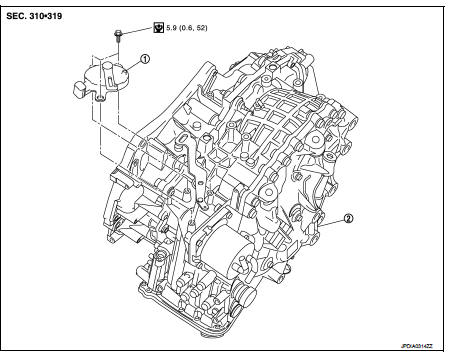
1. Transmission range switch 2. Transaxle assem
Removal and Installation
REMOVAL
1. Remove battery. Refer to PG-124, "Removal and Installation".
2. Remove transmission range switch connector.
3. Remove control cable. Refer to TM-273, "Removal and Installation".
4. Remove transmission range switch from transaxle assembly.
INSTALLATION
Install in the reverse order of removal.
Inspection and Adjustment
ADJUSTMENT OF TRANSMISSION RANGE SWITCH
1. Move selector lever to “N” position.
2. Remove control cable from manual lever.
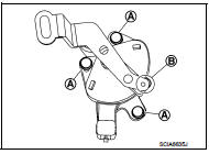
3. Loosen mounting bolts (A) of transmission range switch. Insert a pin (φ4 mm) into the adjusting holes (B) on both transmission range switch and manual lever for adjusting the position.
4. Tighten mounting bolts of transmission range switch.
5. Connect control cable on manual lever. Refer to TM-194, "Inspection and Adjustment".
ADJUSTMENT AFTER INSTALLATION
Adjust the CVT positions after installing the CVT shift selector. Refer to TM-194, "Inspection and Adjustment".
INSPECTION AFTER INSTALLAION
Check the CVT positions after adjusting the CVT positions. Refer to TM-194, "Inspection and Adjustment".
 Key interlock cable
Exploded View
1. CVT shift selector assembly
2. Key interlock cable
A: Key cylinder
B: Clip
C: Clip
Removal and Installation
REMOVAL
CAUTION:
Always apply the parking brake before perfor ...
 TCM
TCM
Exploded View
1. Bracket
2. TCM
:Vehicle front
: N·m (kg-m, in-lb)
Removal and Installation
NOTE:
When replacing TCM and transaxle assembly as a set, replace transaxle assembly
first and t ...
Other materials:
Sun visors
TILT OPERATION
Push the lock lever down 1 and adjust the steering wheel up or down 2 to the
desired position.
Pull the lock lever up 3 securely to lock the steering wheel in place.
1. To block out glare from the front, swing down the sun visor1 .
2. To block glare from the side, remove the ...
U1117 lost communication (ABS)
Description
CAN (Controller Area Network) is a serial communication line for real-time
application. It is an on-vehicle multiplex
communication line with high data communication speed and excellent malfunction
detection ability.
Many electronic control units are equipped onto a vehicle, and ...
How to select piston and bearing
Description
• The identification grade stamped on each part is the grade for the
dimension measured in new condition. This grade cannot apply to reused parts.
• For reused or repaired parts, measure the dimension accurately. Determine the
grade by comparing the
measurement with the values o ...
