Nissan Juke Service and Repair Manual : Interior room lamp power supply circuit
Description
Provides the interior room lamp power supply. Also cuts the power supply when the interior room lamp battery saver activating.
Component Function Check
1.CHECK INTERIOR ROOM LAMP POWER SUPPLY FUNCTION
 CONSULT-III ACTIVE TEST
1. Turn ignition switch ON.
2. Turn each interior room lamp ON.
- Map lamp
- Luggage room lamp
3. Select “BATTERY SAVER” of BCM (BATTERY SAVER) active test item.
4. With operating the test items, check that each interior room lamp turns ON/OFF.
Off : Interior room lamp OFF On : Interior room lamp ON
Does each interior room lamp turn ON/OFF? YES >> Interior room lamp power supply circuit is normal.
NO >> Refer to INL-28, "Diagnosis Procedure".
Diagnosis Procedure
1.CHECK INTERIOR ROOM LAMP POWER SUPPLY OUTPUT
 CONSULT-III ACTIVE TEST
1. Turn ignition switch OFF.
2. Disconnect the following connectors.
- Map lamp
- Luggage room lamp
3. Turn ignition switch ON.
4. Select “BATTERY SAVER” of BCM (BATTERY SAVER) active test item.
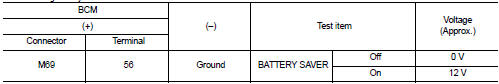
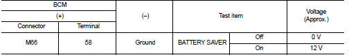
5. With operating the test item, check voltage between BCM harness connector and ground.
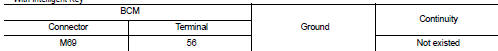
With Intelligent Key
Without Intelligent Key
Is the inspection result normal? YES >> GO TO 2.
NO >> GO TO 3.
2.CHECK INTERIOR ROOM LAMP POWER SUPPLY OPEN CIRCUIT
1. Turn ignition switch OFF.
2. Disconnect the BCM connector.
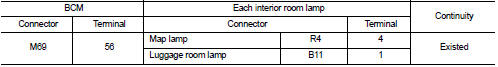
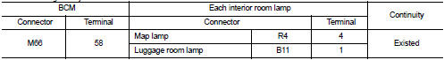
3. Check continuity between BCM harness connector and each interior room lamp harness connector.
With Intelligent Key
Without Intelligent Key
Is the inspection result normal? YES >> Check for internal short circuit of each interior room lamp.
NO >> Repair or replace harnesses.
3.CHECK INTERIOR ROOM LAMP POWER SUPPLY SHORT CIRCUIT
1. Turn ignition switch OFF.
2. Disconnect the BCM connector.
3. Check continuity between BCM harness connector and ground.
With Intelligent Key
Without Intelligent Key

Is the inspection result normal? YES >> Replace BCM. Refer to BCS-93, "Removal and Installation".
NO >> Repair or replace harnesses.

 Interior room lamp control circuit
Description
Controls each interior room lamp (ground side) by PWM signal.
NOTE:
PWM signal control period is approximately 250 Hz (in the gradual
brightening/dimming).
Component Function Check ...
Other materials:
P1740 select solenoid
DTC Logic
DTC DETECTION LOGIC
DTC CONFIRMATION PROCEDURE
CAUTION:
Always drive vehicle at a safe speed.
NOTE:
If “DTC CONFIRMATION PROCEDURE” has been previously performed, always turn
ignition switch
OFF and wait at least 10 seconds before performing the next test.
After the repair, p ...
MDU branch line circuit
Diagnosis Procedure
1.CHECK CONNECTOR
1. Turn the ignition switch OFF.
2. Disconnect the battery cable from the negative terminal.
3. Check the terminals and connectors of the multi display unit for damage, bend
and loose connection (unit
side and connector side).
Is the inspection result ...
Wiper and washer system symptoms
With rain sensor
WITH RAIN SENSOR : Symptom Table
Without rain sensor
WITHOUT RAIN SENSOR : Symptom Table
...
