Nissan Juke Service and Repair Manual : Interior room lamp control circuit
Description
Controls each interior room lamp (ground side) by PWM signal.
NOTE
:
PWM signal control period is approximately 250 Hz (in the gradual
brightening/dimming).
Component Function Check
CAUTION:
Before performing the diagnosis, check that the following are normal.
• Interior room lamp power supply • Map lamp bulb
1.CHECK INTERIOR ROOM LAMP CONTROL FUNCTION
 CONSULT-III ACTIVE TEST
1. Switch the map lamp switch to DOOR.
2. Turn ignition switch ON.
3. Select “INT LAMP” of BCM (INT LAMP) active test item.
4. With operating the test items, check that each interior room lamp turns ON/OFF (gradual brightening/dimming).
On : Interior room lamp gradual brightening Off : Interior room lamp gradual dimming
Does the interior room lamp turns ON/OFF (gradual brightening/dimming)? YES >> Interior room lamp control circuit is normal.
NO >> Refer to INL-30, "Diagnosis Procedure".
Diagnosis Procedure
1.CHECK INTERIOR ROOM LAMP CONTROL OUTPUT
 CONSULT-III ACTIVE TEST
1. Turn ignition switch OFF.
2. Remove all the bulbs of map lamp.
3. Turn ignition switch ON.
4. Select “INT LAMP” of BCM (INT LAMP) active test item.
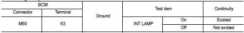
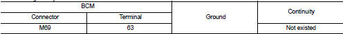
5. With operating the test item, check continuity between BCM harness connector and ground.
With Intelligent Key
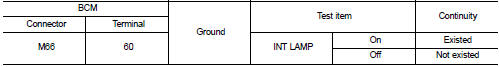
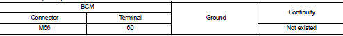
Without Intelligent Key
Is the inspection result normal? YES >> GO TO 2.
Fixed ON>>GO TO 3.
Fixed OFF>>Replace BCM. Refer to BCS-93, "Removal and Installation".
2.CHECK INTERIOR ROOM LAMP CONTROL OPEN CIRCUIT
1. Turn ignition switch OFF.
2. Disconnect BCM connector, map lamp connector.
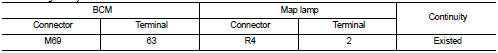
3. Check continuity between BCM harness connector and map lamp harness connector.
With Intelligent Key
Without Intelligen
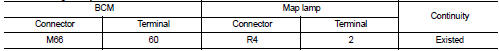
Is the inspection result normal? YES >> Replace map lamp.Refer to INL-37, "Removal and Installation".
NO >> Repair or replace harnesses.
3.CHECK INTERIOR ROOM LAMP CONTROL SHORT CIRCUIT
1. Turn ignition switch OFF.
2. Disconnect BCM connector and map lamp connector.
3. Check continuity between BCM harness connector and ground.
With Intelligent Key
Without Intelligent Key
Is the inspection result normal? YES >> Replace BCM. Refer to BCS-93, "Removal and Installation".
NO >> Repair or replace harnesses.
 Interior room lamp power supply circuit
Description
Provides the interior room lamp power supply. Also cuts the power supply when
the interior room lamp battery
saver activating.
Component Function Check
1.CHECK INTERIOR ROOM LAMP POW ...
 Luggage room lamp circuit
Description
Controls the luggage room lamp (ground side) to turn the luggage room lamp ON
and OFF.
Diagnosis Procedure
CAUTION:
Before performing the diagnosis, check that the following are norm ...
Other materials:
Diagnosis and repair workflow
Work Flow
OVERALL SEQUENCE
DETAILED FLOW
1.INTERVIEW FOR MALFUNCTION
Interview the symptom to the customer
>> GO TO 2.
2.SYMPTOM CHECK
Check the symptom from the customer's information. Check that any symptom
occurs other than the interviewed
symptom.
Insufficient cooling/heat ...
B260C steering lock unit
DTC Logic
DTC DETECTION LOGIC
DTC CONFIRMATION PROCEDURE
1.PERFORM DTC CONFIRMATION PROCEDURE
1. Shift selector lever to the P position.
2. Press push-button ignition switch under the following condition.
- Brake pedal: Not depressed
3. Turn ignition switch ON.
4. Turn ignition switch OFF. ...
Component parts
Component Parts Location
1. Combination meter
2. Key switch
3. BCM
Refer to BCS-96, "BODY CONTROL
SYSTEM : Component Parts Location"
4. Power window main switch
(door lock/unlock switch)
5. Front door switch (driver side)
6. Front door lock assembly (driver
side)
7. Back do ...
