Nissan Juke Service and Repair Manual : Illumination
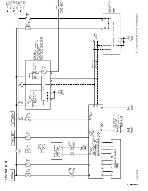
Wiring Diagram
For connector terminal arrangements, harness layouts, and alphabets in a
 (option abbreviation: if not
described in wiring diagram), refer to GI-12, "Connector Information/Explanation
of Option Abbreviation".
 Interior room lamp control system
Wiring Diagram
For connector terminal arrangements, harness layouts, and alphabets in a
(option abbreviation: if not
described in wiring diagram), refer to GI-12, "Connector Information/Explan ...
 Basic inspection
DIAGNOSIS AND REPAIR WORKFLOW
Work Flow
OVERALL SEQUENCE
DETAILED FLOW
1.INTERVIEW FOR MALFUNCTION
Interview the symptom to the customer.
>> GO TO 2.
2.SYMPTOM CHECK
Check the sympto ...
Other materials:
P0133 A/F sensor 1
DTC Logic
DTC DETECTION LOGIC
To judge the malfunction of A/F sensor 1, this diagnosis measures response
time of the A/F signal computed
by ECM from the A/F sensor 1 signal. The time is compensated by engine operating
(speed and load), fuel
feedback control constant, and the A/F sensor 1 tem ...
P0506 ISC system
Description
The ECM controls the engine idle speed to a specified level through the fine
adjustment of the air, which is let
into the intake manifold, by operating the electric throttle control actuator.
The operating of the throttle valve is
varied to allow for optimum control of the engine ...
Air conditioner filter
Exploded View
LHD models
1. A/C unit assembly
2. Air conditioner filter
3. Filter cover
Removal and Installation (LHD models)
REMOVAL
1. Remove glove box assembly. Refer to IP-13, "Removal and Installation".
2. Remove filter cover (1), and then remove air conditioner filter (2) ...
