Nissan Juke Service and Repair Manual : P0133 A/F sensor 1
DTC Logic
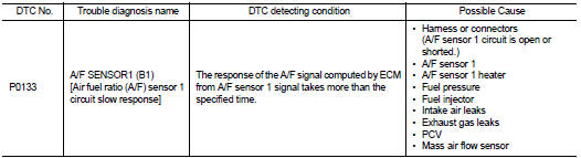
DTC DETECTION LOGIC
To judge the malfunction of A/F sensor 1, this diagnosis measures response time of the A/F signal computed by ECM from the A/F sensor 1 signal. The time is compensated by engine operating (speed and load), fuel feedback control constant, and the A/F sensor 1 temperature index. Judgment is based on whether the compensated time (the A/F signal cycling time index) is inordinately long or not.
DTC CONFIRMATION PROCEDURE
1.PRECONDITIONING
If DTC Confirmation Procedure has been previously conducted, always perform the following procedure before conducting the next test.
1. Turn ignition switch OFF and wait at least 10 seconds.
2. Turn ignition switch ON.
3. Turn ignition switch OFF and wait at least 10 seconds.
TESTING CONDITION:
Before performing the following procedure, confirm that battery voltage is more
than 11 V at idle.
Do you have CONSULT-III? YES >> GO TO 2.
NO >> GO TO 5.
2.PERFORM DTC CONFIRMATION PROCEDURE-I
 With CONSULT-III
1. Start engine and warm it up to normal operating temperature.
2. Turn ignition switch OFF and wait at least 10 seconds.
3. Restart engine and keep the engine speed between 3,500 and 4,000 rpm for at least 1minute under no load.
4. Let engine idle for 1 minute.
5. Select “ENGINE” using CONSULT-III.
6. Select “A/F SEN1(B1) P1278/P1279” (for DTC P0133) of “A/F SEN1” in “DTC WORK SUPPORT” mode.
7. Touch “START”.
Is “COMPLETED” displayed on CONSULT-III screen? YES >> GO TO 3 NO >> GO TO 4.
3.PERFORM DTC CONFIRMATION PROCEDURE-II
Touch “SELF-DIAG RESULT”.
Which is displayed on CONSULT-III screen? OK >> INSPECTION END
NG >> Proceed to EC-216, "Diagnosis Procedure".
4.PERFORM DTC CONFIRMATION PROCEDURE-II
1. After perform the following procedure, “TESTING” will be displayed on the CONSULT-III screen.
- Increase the engine speed up to between 4,000 and 5,000 rpm and maintain that speed for 10 seconds.
- Fully release accelerator pedal and then let engine idle for about 10 seconds.
If “TESTING” is not displayed after 10 seconds, refer to EC-558, "Component Function Check".
2. Wait for about 20 seconds at idle as per the condition that “TESTING” is displayed on the CONSULT-III screen.
3. Make sure that “TESTING” changes to “COMPLETED”.
If “TESTING” changed to “OUT OF CONDITION”, refer to EC-558, "Component Function Check".
4. Touch “SELF-DIAG RESULT”.
Which is displayed on CONSULT-III screen? OK >> INSPECTION END
NG >> Proceed to EC-216, "Diagnosis Procedure".
5.CHECK AIR-FUEL RATIO SELF-LEARNING VALUE
 With GST
1. Start engine and warm it up to normal operating temperature.
2. Select Service $01 with GST.
3. Calculate the total value of “Short term fuel trim” and “Long term fuel trim” indications.
Is the total percentage within ±15%? YES >> GO TO 7.
NO >> GO TO 6.
6.DETECT MALFUNCTIONING PART
Check the following.
• Intake air leaks
• Exhaust gas leaks
• Incorrect fuel pressure
• Lack of fuel
• Fuel injector
• Incorrect PCV hose connection
• PCV valve
• Mass air flow sensor
>> Repair or replace malfunctioning part.
7.PERFORM DTC CONFIRMATION PROCEDURE
1. Turn ignition switch OFF and wait at least 10 seconds.
2. Restart engine and keep the engine speed between 3,500 and 4,000 rpm for at least 1minute under no load.
3. Let engine idle for 1 minute.
4. Increase the engine speed up to between 4,000 and 5,000 rpm and maintain that speed for 10 seconds.
5. Fully release accelerator pedal and then let engine idle for about 1 minute.
6. Check 1st trip DTC.
Is 1st trip DTC detected? YES >> Proceed to EC-216, "Diagnosis Procedure".
NO >> INSPECTION END
Component Inspection
1.RETIGHTEN A/F SENSOR 1
Loosen and retighten the A/F sensor 1. Refer to EM-166, "Exploded View".
>> GO TO 2.
2.CHECK EXHAUST GAS LEAK
1. Start engine and run it at idle.
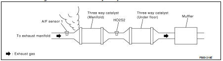
2. Listen for an exhaust gas leak before three way catalyst 1.
Is exhaust gas leak detected? YES >> Repair or replace.
NO >> GO TO 3.
3.CHECK FOR INTAKE AIR LEAK
Listen for an intake air leak after the mass air flow sensor.
Is intake air leak detected? YES >> Repair or replace.
NO >> GO TO 4.
4.CLEAR THE MIXTURE RATIO SELF-LEARNING VALUE
1. Clear the mixture ratio self-learning value. Refer to EC-546, "Work Procedure".
2. Run engine for at least 10 minutes at idle speed.
Is the 1st trip DTC P0171 or P0172 detected? Is it difficult to start engine? YES >> Perform trouble diagnosis for DTC P0171 or P0172. Refer to EC-635, "DTC Logic" or EC-639, "DTC Logic".
NO >> GO TO 5.
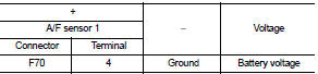
5.CHECK AIR FUEL RATIO (A/F) SENSOR 1 POWER SUPPLY
1. Turn ignition switch OFF.
2. Disconnect A/F sensor 1 harness connector.
3. Turn ignition switch ON.
4. Check the voltage between A/F sensor 1 harness connector and ground.
Is the inspection result normal? YES >> GO TO 7.
NO >> GO TO 6.
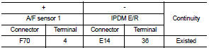
6.CHECK A/F SENSOR 1 INPUT SIGNAL CIRCUIT
1. Turn ignition switch OFF.
2. Disconnect IPDM E/R harness connector.
3. Check the continuity between A/F sensor 1 harness connector and IPDM E/R harness connector.
4. Also check harness for short to ground.
Is the inspection result normal? YES >> Perform the trouble diagnosis for power supply circuit.
NO >> Repair or replace error-detected parts.
7.CHECK A/F SENSOR 1 INPUT SIGNAL CIRCUIT
1. Turn ignition switch OFF.
2. Disconnect ECM harness connector.
3. Check the continuity between A/F sensor 1 harness connector and ECM harness connector.
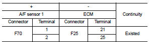
4. Check the continuity between A/F sensor 1 harness connector and ground or ECM harness connector and ground.
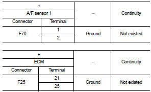
5. Also check harness for short to power.
Is the inspection result normal? YES >> GO TO 8.
NO >> Repair or replace error-detected parts.
8.CHECK AIR FUEL RATIO (A/F) SENSOR 1 HEATER
Check the air fuel ratio (a/f) sensor 1 heater. Refer to EC-578, "Component Inspection".
Is the inspection result normal? YES >> GO TO 9.
NO >> GO TO 12.
9.CHECK MASS AIR FLOW SENSOR
Check the mass air flow sensor. Refer to EC-590, "Component Inspection".
Is the inspection result normal? YES >> GO TO 10.
NO >> Replace mass air flow sensor. Refer to EM-26, "Exploded View".
10.CHECK PCV VALVE
Check the PCV valve. Refer to EC-804, "Inspection".
Is the inspection result normal? YES >> GO TO 11.
NO >> Repair or replace PCV valve. Refer to EM-53, "Exploded View".
11.CHECK INTERMITTENT INCIDENT
Perform GI-42, "Intermittent Incident".
Is the inspection result normal?
YES >> GO TO 12.
NO >> Repair or replace error-detected parts.
12.REPLACE AIR FUEL RATIO (A/F) SENSOR 1
Replace malfunctioning air fuel ratio (A/F) sensor 1. Refer to EM-38, "Exploded View".
CAUTION:
• Discard any A/F sensor which has been dropped from a height of more than 0.5 m
(19.7 in) onto a
hard surface such as a concrete floor; use a new one.
• Before installing new A/F sensor, clean exhaust system threads using Oxygen Sensor Thread Cleaner (commercial service tool) and approved anti-seize lubricant (commercial service tool).
>> INSPECTION END
 P0132 A/F sensor 1
DTC Logic
DTC DETECTION LOGIC
To judge the malfunction, the diagnosis checks that the A/F signal computed
by ECM from the A/F sensor 1
signal is not inordinately high.
DTC CONFIRMATION PROCEDU ...
 P0137 HO2S2
DTC Logic
DTC DETECTION LOGIC
The heated oxygen sensor 2 has a much longer switching time
between rich and lean than the air fuel ratio (A/F) sensor 1. The oxygen
storage capacity of the three way ...
Other materials:
EPS warning lamp does not turn on
Description
EPS warning lamp does not turn ON when turning ignition switch ON from OFF.
(Check the illumination of the
EPS warning lamp.)
Diagnosis Procedure
1.CHECK EPS WARNING LAMP
Perform the trouble diagnosis of EPS warning lamp. Refer to STC-26,
"Diagnosis Procedure".
Is t ...
Mainshaft and gear
Exploded View
1. Mainshaft front bearing outer
race
2. Mainshaft front bearing inner race
3. Mainshaft
4. 1st main gear
5. 1st inner baulk ring
6. 1st synchronizer cone
7. 1st outer baulk ring
8. 1st-2nd coupling sleeve
9. Insert key
10. 1st-2nd synchronizer hub
11. 2nd outer baulk ...
B1152 curtain air bag module LH
DTC Logic
DTC DETECTION LOGIC
DTC CONFIRMATION PROCEDURE
1.CHECK SELF-DIAG RESULT
With CONSULT-III
1. Turn ignition switch ON.
2. Perform “Self Diagnostic Result” mode of “AIR BAG” using CONSULT-III.
Without CONSULT-III
1. Turn ignition switch ON.
2. Check the air bag warning lamp statu ...
