Nissan Juke Service and Repair Manual : Front wiper auto stop signal circuit
Component Function Check
1.CHECK FRONT WIPER (AUTO STOP) SIGNAL
 CONSULT-III DATA MONITOR
1. Select “WIP AUTO STOP” of IPDM E/R data monitor item.
2. Operate the front wiper.
3. With the front wiper operation, check the monitor status.
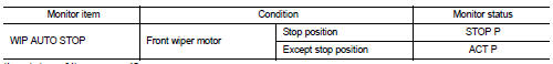
Is the status of item normal? YES >> Auto stop signal circuit is normal.
NO >> Refer to WW-40, "Diagnosis Procedure".
Diagnosis Procedure
1.CHECK IPDM E/R OUTPUT VOLTAGE
1. Turn ignition switch OFF.
2. Disconnect front wiper motor connector.
3. Turn ignition switch ON.
4. Check voltage between front wiper motor harness connector and ground.
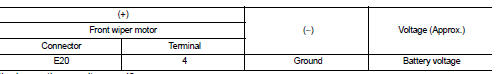
Is the inspection result normal? YES >> Replace front wiper motor.
NO >> GO TO 2.
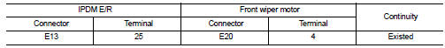
2.CHECK FRONT WIPER MOTOR (AUTO STOP) CIRCUIT
1. Turn ignition switch OFF.
2. Disconnect IPDM E/R connector.
3. Check continuity between IPDM E/R harness connector and front wiper motor harness connector.
4. Check continuity between IPDM E/R harness connector and ground.
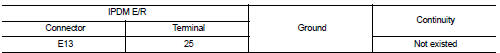
Is the inspection result normal? YES >> Replace IPDM E/R.
NO >> Repair or replace harness.
 Front wiper motor hi circuit
Component Function Check
1.CHECK FRONT WIPER HI OPERATION
CONSULT-III ACTIVE TEST
1. Select “FRONT WIPER” of IPDM E/R active test item.
2. With operating the test item, check front wiper operation ...
 Front wiper motor ground circuit
Diagnosis Procedure
1.CHECK FRONT WIPER MOTOR GROUND CIRCUIT
1. Turn ignition switch OFF.
2. Disconnect front wiper motor connector.
3. Check continuity between front wiper motor harness connector ...
Other materials:
Exploded View
1. Mounting rubber
2. Main muffler
3. Seal bearing
4. Spring
5. Mounting rubber
6. Seal bearing
7. Exhaust front tube
8. Heated oxygen sensor 2
9. Sub muffler
10. Gasket
: Always replace after every
disassembly.
: N·m (kg-m, ft-lb)
...
Exhaust valve timing control
Exhaust valve timing control : System Diagram
Exhaust valve timing control: System Description
INPUT/OUTPUT SIGNAL CHART
SYSTEM DESCRIPTION
This mechanism hydraulically controls cam phases continuously with the fixed
operating angle of the exhaust
valve.
The ECM receives signals such ...
P1553 battery current sensor
DTC Logic
DTC DETECTION LOGIC
DTC CONFIRMATION PROCEDURE
1.PRECONDITIONING
If DTC Confirmation Procedure has been previously conducted, always perform
the following before conducting
the next test.
1. Turn ignition switch OFF and wait at least 10 seconds.
2. Turn ignition switch ON.
3. ...
