Nissan Juke Service and Repair Manual : Exhaust valve timing control
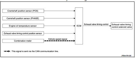
Exhaust valve timing control : System Diagram
Exhaust valve timing control: System Description
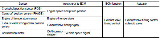
INPUT/OUTPUT SIGNAL CHART
SYSTEM DESCRIPTION
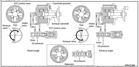
This mechanism hydraulically controls cam phases continuously with the fixed operating angle of the exhaust valve.
The ECM receives signals such as crankshaft position, camshaft position, engine speed, and engine oil temperature.
Then, the ECM sends ON/OFF pulse duty signals to the exhaust valve timing (EVT) control solenoid valve depending on driving status. This makes it possible to control the shut/open timing of the exhaust valve to increase engine torque and output in a range of high engine speed.
 Intake valve timing control
Intake valve timing control : System Diagram
Intake valve timing control : System Description
INPUT/OUTPUT SIGNAL CHART
SYSTEM DESCRIPTION
This mechanism hydraulically controls cam phases co ...
 Turbocharger boost control
Turbocharger boost control : SystemDiagram
Turbocharger boost control : System Description
INPUT/OUTPUT SIGNAL CHART
SYSTEM DESCRIPTION
Depending on driving conditions, the ECM performs ON/OFF ...
Other materials:
Recommended fluids and lubricants
Fluids and Lubricants
*1: For additional information, see “SAE Viscosity Number”.
*2: Use Genuine NISSAN Engine Coolant or equivalent in its quality, in order to
avoid possible aluminium corrosion within the engine
cooling system caused by the use of non-genuine engine coolant. Note that any ...
Ecu diagnosis information
TCM
Reference Value
CONSULT-III DATA MONITOR STANDARD VALUE
• In CONSULT-III, electric shift timing or lock-up timing, i.e. operation
timing of each solenoid valve, is displayed.
Therefore, if there is an obvious difference between the shift timing estimated
from a shift shock (or
engine ...
Keyfob battery
Exploded View
1. Upper case
2. Key
3. Switch cover
4. Switch rubber
5. Board surface
6. Battery
7. plate
8. Lower case
9. Screw
Removal and Installation
REMOVAL
1. Remove screw (9) on the rear of keyfob.
2. Place the key with the lower case (8) facing up. Set a screw-driver wrap ...
