Nissan Juke Service and Repair Manual : Door lock actuator
Driver side
DRIVER SIDE : Component Function Check
1.CHECK FUNCTION
1. Select “DOOR LOCK” of “BCM” using CONSULT-III.
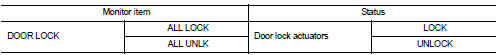
2. Select “DOOR LOCK” in “ACTIVE TEST” mode.
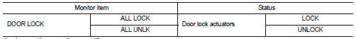
3. Check that the function operates normally according to the following conditions.
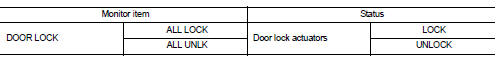
Is the inspection result normal? YES >> Door lock actuator is OK.
NO >> Refer to DLK-249, "DRIVER SIDE : Diagnosis Procedure".
DRIVER SIDE : Diagnosis Procedure
1.CHECK DOOR LOCK ACTUATOR INPUT SIGNAL
1. Turn ignition switch OFF.
2. Disconnect front door lock assembly (driver side) connector.
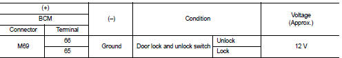
3. Check voltage between front door lock assembly (driver side) harness connector and ground.
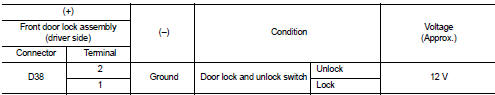
Is the inspection result normal? YES >> Replace front door lock assembly (driver side).
NO >> GO TO 2.
2.CHECK DOOR LOCK ACTUATOR CIRCUIT
1. Disconnect BCM connector and all door lock assembly connector.
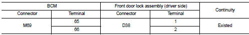
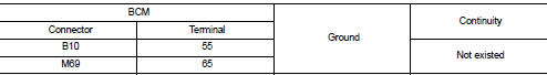
2. Check continuity between BCM harness connector and front door lock assembly (driver side) harness connector.
3. Check continuity between BCM harness connector and ground.
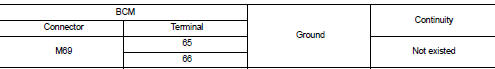
Is the inspection result normal? YES >> GO TO 3.
NO >> Repair or replace harness.
3.CHECK BCM OUTPUT SIGNAL
1. Connect BCM connector.
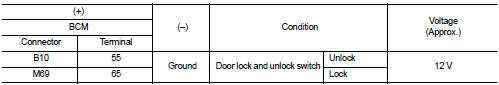
2. Check voltage between BCM harness connector and ground.
Is the inspection result normal? YES >> Check for internal short of each door lock actuator.
NO >> Replace BCM. Refer to BCS-93, "Removal and Installation".
Passenger side
PASSENGER SIDE : Component Function Check
1.CHECK FUNCTION
1. Select “DOOR LOCK” of “BCM” using CONSULT-III.
2. Select “DOOR LOCK” in “ACTIVE TEST” mode.
3. Check that the function operates normally according to the following conditions.
Is the inspection result normal? YES >> Door lock actuator is OK.
NO >> Refer to DLK-249, "DRIVER SIDE : Diagnosis Procedure".
PASSENGER SIDE : Diagnosis Procedure
1.CHECK DOOR LOCK ACTUATOR INPUT SIGNAL
1. Turn ignition switch OFF.
2. Disconnect front door lock assembly (passenger side) connector.
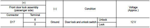
3. Check voltage between front door lock assembly (passenger side) harness connector and ground.
Is the inspection result normal? YES >> Replace front door lock assembly (passenger side).
NO >> GO TO 2.
2.CHECK DOOR LOCK ACTUATOR CIRCUIT
1. Disconnect BCM connector and all door lock assembly connector.
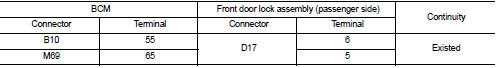
2. Check continuity between BCM harness connector and front door lock assembly (passenger side) harness connector.
3. Check continuity between BCM harness connector and ground.
Is the inspection result normal? YES >> GO TO 3.
NO >> Repair or replace harness.
3.CHECK BCM OUTPUT SIGNAL
1. Connect BCM connector.
2. Check voltage between BCM harness connector and ground.
Is the inspection result normal? YES >> Check for internal short of each door lock actuator.
NO >> Replace BCM. Refer to BCS-93, "Removal and Installation".
Rear LH
REAR LH : Component Function Check
1.CHECK FUNCTION
1. Select “DOOR LOCK” of “BCM” using CONSULT-III.
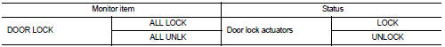
2. Select “DOOR LOCK” in “ACTIVE TEST” mode.
3. Check that the function operates normally according to the following conditions.
Is the inspection result normal? YES >> Door lock actuator is OK.
NO >> Refer to DLK-249, "DRIVER SIDE : Diagnosis Procedure".
REAR LH : Diagnosis Procedure
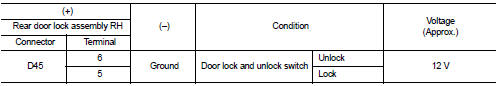
1.CHECK DOOR LOCK ACTUATOR INPUT SIGNAL
1. Turn ignition switch OFF.
2. Disconnect rear door lock assembly LH connector.
3. Check voltage between rear door lock assembly LH harness connector and ground.
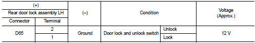
Is the inspection result normal? YES >> Replace rear door lock assembly LH.
NO >> GO TO 2.
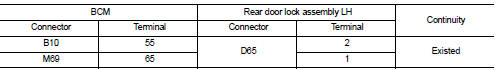
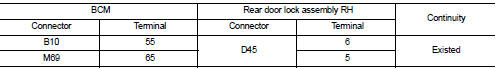
2.CHECK DOOR LOCK ACTUATOR CIRCUIT
1. Disconnect BCM connector and all door lock assembly connector.
2. Check continuity between BCM harness connector and rear door lock assembly LH harness connector.
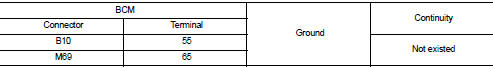
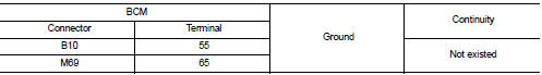
3. Check continuity between BCM harness connector and ground.
Is the inspection result normal? YES >> GO TO 3.
NO >> Repair or replace harness.
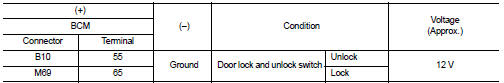
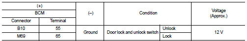
3.CHECK BCM OUTPUT SIGNAL
1. Connect BCM connector.
2. Check voltage between BCM harness connector and ground.
Is the inspection result normal? YES >> Check for internal short of each door lock actuator.
NO >> Replace BCM. Refer to BCS-93, "Removal and Installation".
Rear RH
REAR RH : Component Function Check
1.CHECK FUNCTION
1. Select “DOOR LOCK” of “BCM” using CONSULT-III.
2. Select “DOOR LOCK” in “ACTIVE TEST” mode.
3. Check that the function operates normally according to the following conditions.
Is the inspection result normal? YES >> Door lock actuator is OK.
NO >> Refer to DLK-249, "DRIVER SIDE : Diagnosis Procedure".
REAR RH : Diagnosis Procedure
1.CHECK DOOR LOCK ACTUATOR INPUT SIGNAL
1. Turn ignition switch OFF.
2. Disconnect rear door lock assembly RH connector.
3. Check voltage between rear door lock assembly RH harness connector and ground.
Is the inspection result normal? YES >> Replace rear door lock assembly RH.
NO >> GO TO 2.
2.CHECK DOOR LOCK ACTUATOR CIRCUIT
1. Disconnect BCM connector and all door lock assembly connector.
2. Check continuity between BCM harness connector and rear door lock assembly RH harness connector.
3. Check continuity between BCM harness connector and ground.
Is the inspection result normal? YES >> GO TO 3.
NO >> Repair or replace harness.
3.CHECK BCM OUTPUT SIGNAL
1. Connect BCM connector.
2. Check voltage between BCM harness connector and ground.
Is the inspection result normal? YES >> Check for internal short of each door lock actuator.
NO >> Replace BCM. Refer to BCS-93, "Removal and Installation".
 Buzzer (combination meter)
Component Function Check
1.CHECK FUNCTION
1. Select “INTELLIGENT KEY” of “BCM” using CONSULT-III.
2. Select “INSIDE BUZZER” in “ACTIVE TEST” mode.
3. Check that the function operates normally acco ...
 Door lock and unlock switch
Component Function Check
1.CHECK FUNCTION
1. Select “DOOR LOCK” of “BCM” using CONSULT-III.
2. Select “CDL LOCK SW”, “CDL UNLOCK SW” in “DATA MONITOR” mode.
3. Check that the function operates nor ...
Other materials:
Passenger side door mirror defogger
Description
Heats the heating wire with the power supply from the rear window defogger
relay to prevent the door mirror
from fogging up.
Component Function Check
1.CHECK PASSENGER SIDE DOOR MIRROR DEFOGGER
1. Perform IPDM E/R Active Test (“REAR DEFOGGER”) using CONSULT-III.
2. Touch “ON”.
3 ...
Headlamp washer nozzle and tube
Exploded View
1. Washer tank
2. Headlamp washer tube (tank side)
3. Headlamp washer tube RH
4. Headlamp washer nozzle connector
RH
5. Headlamp washer nozzle bracket RH
6. Headlamp washer nozzle RH
7. Headlamp washer nozzle joint
8. Headlamp washer nozzle bracket LH
9. Headlamp washe ...
Fluid cooler system
Exploded View
1. Copper washer
2. CVT fluid cooler tube
3. Hose clamp
4. Fluid cooler hose A
5. Fluid cooler tube
6. Fluid cooler hose B
7. Fluid cooler hose C
8. Transaxle assembly
9. Fluid cooler hose D
10. Fluid cooler hose E
11. Fluid cooler hose F
12. Bypass valve
13. Flu ...
