Nissan Juke Service and Repair Manual : Door lock and unlock switch
Component Function Check
1.CHECK FUNCTION
1. Select “DOOR LOCK” of “BCM” using CONSULT-III.
2. Select “CDL LOCK SW”, “CDL UNLOCK SW” in “DATA MONITOR” mode.
3. Check that the function operates normally according to the following conditions.
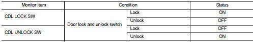
Is the inspection result normal? YES >> Door lock and unlock switch is OK.
NO >> Refer to DLK-254, "Diagnosis Procedure".
Diagnosis Procedure
1.CHECK DOOR LOCK AND UNLOCK SWITCH INPUT SIGNAL
1. Turn ignition switch OFF.
2. Disconnect power window main switch connector.
3. Check signal between power window main switch harness connector and ground using oscilloscope.
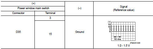
Is the inspection result normal? YES >> GO TO 3.
NO >> GO TO 2.
2.CHECK DOOR LOCK AND UNLOCK SWITCH CIRCUIT
1. Disconnect BCM connector and front power window switch (passenger side) connector.
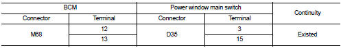
2. Check continuity between BCM harness connector and power window main switch harness connector.
3. Check continuity between BCM harness connector and ground.
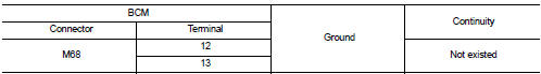
Is the inspection result normal? YES >> Replace BCM. Refer to BCS-93, "Removal and Installation".
NO >> Repair or replace harness.
3.CHECK DOOR LOCK AND UNLOCK SWITCH GROUND
Check continuity between power window main switch harness connector and ground.
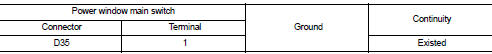
Is the inspection result normal? YES >> GO TO 4.
NO >> Repair or replace harness.
4.CHECK DOOR LOCK AND UNLOCK SWITCH
Refer to DLK-255, "Component Inspection".
Is the inspection result normal? YES >> GO TO 5.
NO >> Replace power window main switch. Refer to PWC-44, "Removal and Installation".
5.CHECK INTERMITTENT INCIDENT
Refer to GI-42, "Intermittent Incident".
>> INSPECTION END
Component Inspection
1.CHECK DOOR LOCK AND UNLOCK SWITCH
1. Turn ignition switch OFF.
2. Disconnect power window main switch connector.
3. Check continuity between power window main switch terminals.
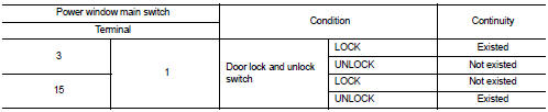
Is the inspection result normal? YES >> INSPECTION END
NO >> Replace power window main switch.
 Door lock actuator
Driver side
DRIVER SIDE : Component Function Check
1.CHECK FUNCTION
1. Select “DOOR LOCK” of “BCM” using CONSULT-III.
2. Select “DOOR LOCK” in “ACTIVE TEST” mode.
3. Check that the function opera ...
 Door request switch
Component Function Check
1.CHECK FUNCTION
1. Select “INTELLIGENT KEY” of “BCM” using CONSULT-III.
2. Select “REQ SW-DR”, “REQ SW-AS” in “DATA MONITOR” mode.
3. Check that the function operates nor ...
Other materials:
B2627 outside antenna
DTC Logic
DTC DETECTION LOGIC
DTC CONFIRMATION PROCEDURE
1.PERFORM DTC CONFIRMATION PROCEDURE
1. Disconnect outside key antenna (passenger side) connector.
2. Perform “INTELLIGENT KEY” Self Diagnostic Result.
Is outside key antenna DTC detected?
YES >> Refer to DLK-63, "Diagnos ...
Headlamp washer system
Wiring Diagram - HEADLAMP WASHER SYSTEM -
For connector terminal arrangements, harness layouts, and alphabets in a
(option abbreviation; if not
described in wiring diagram), refer to GI-12, "Connector Information/Explanation
of Option Abbreviation".
...
P0122, P0123 TP sensor
DTC Logic
DTC DETECTION LOGIC
NOTE:
If DTC P0122 or P0123 is displayed with DTC P0643, first perform the trouble
diagnosis for DTC P0643.
Refer to EC-307, "DTC Logic".
DTC CONFIRMATION PROCEDURE
1.PRECONDITIONING
If DTC Confirmation Procedure has been previously conducted, alw ...
