Nissan Juke Service and Repair Manual : Fluid cooler system
Exploded View
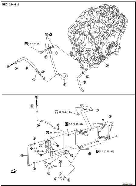
1. Copper washer
2. CVT fluid cooler tube
3. Hose clamp
4. Fluid cooler hose A
5. Fluid cooler tube
6. Fluid cooler hose B
7. Fluid cooler hose C
8. Transaxle assembly
9. Fluid cooler hose D
10. Fluid cooler hose E
11. Fluid cooler hose F
12. Bypass valve
13. Fluid cooler
14. Air guide
15. Bracket A
16. Bracket B
A. To radiator
 : Vehicle side
Removal and Installation
REMOVAL
1. Remove engine under cover.
2. Remove front bumper assembly. Refer to EXT-13, "Removal and Installation".
3. Remove air guide from fluid cooler.
4. Remove fluid cooler hose E and fluid cooler hose F.
5. Remove fluid cooler.
6. Remove air duct (inlet). Refer to EM-26, "Removal and Installation".
7. Remove fluid cooler hose C and fluid cooler hose D.
8. Remove bypass valve from bracket B.
9. Remove fluid cooler hose A and fluid cooler hose B.
10. Remove fluid cooler tube.
11. Remove bracket A and bracket B.
12. Remove CVT fluid cooler tube from transaxle assembly.
INSTALLATION
Note the following, and install in the reverse order of removal.
CAUTION:
Never reuse copper washer.
• When installing CVT fluid cooler tube (1) to transaxle assembly: - Contact CVT fluid cooler tube a boss portion (A) of the transaxle case.
- Tighten the bolt of CVT fluid cooler tube without moving the CVT fluid cooler tube
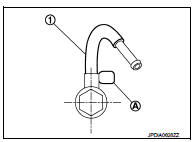
• Refer to the followings when installing fluid cooler hose.
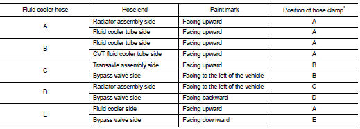
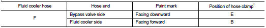
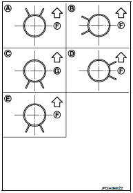
*: Refer to the illustrations for the specific position each hose clamp tab.
- The illustrations indicate the view from the hose ends.
F : Vehicle upper
 G : Vehicle front
- When installing hose clamps center line of each hose clamp tab should be positioned as shown in the figure.
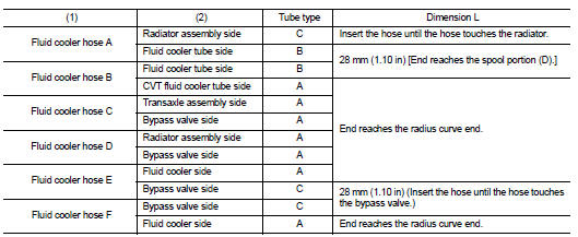
- Insert fluid cooler hose according to dimension (L) described below.
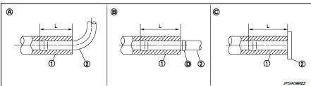
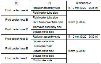
- Set hose clamps (1) at the both ends of fluid cooler hose (2) with dimension (A) from the hose edge.
- Hose clamp should not interfere with the bulge of fluid cooler tube.
Inspection
INSPECTION AFTER INSTALLATION
Check for CVT fluid leakage and CVT fluid level. Refer to TM-184, "Inspection".
 Water hose
Exploded View
1. Hose clamp
2. Water hose
A. Water outlet
B. Oil warm
Removal and Installation
REMOVAL
WARNING:
Never remove the radiator cap when the engine is hot. Serious burns could oc ...
 Unit removal and installation
Transaxle assembly
Exploded View
1. CVT fluid level gauge
2. CVT fluid charging pipe
3. O-ring
4. Transaxle assembly
5. Air breather hose
A. For tightening torque, refer to TM-301, "R ...
Other materials:
Gas station information
FUEL RECOMMENDATION:
NISSAN recommends the use of unleaded premium gasoline with an octane rating
of at least 91 AKI (Anti-Knock Index) number (Research octane number 96).
If unleaded premium gasoline is not available, you may use unleaded regular gasoline
with an octane rating of at least 87 ...
Additional service when removing battery negative terminal
Description
When the battery negative terminal is disconnected, the initialization is
necessary for normal operation of
power window system.
CAUTION:
The following specified operations can not be performed under the
non-initialized condition.
• Auto-up operation
• Anti-pinch function
Wo ...
Front wiper drive assembly
Exploded View
REMOVAL
LHD models
1. Front wiper arm cap
2. Front wiper arm LH
3. Front wiper blade LH
4. Front wiper arm RH
5. Front wiper blade RH
6. Front wiper drive assembly
: Pawl
: N·m (kg-m, in-lb)
: N·m (kg-m, ft-lb)
RHD models
1. Front wiper arm cap
2. Front wiper arm ...
