Nissan Juke Service and Repair Manual : Compressor
Exploded View
REMOVAL
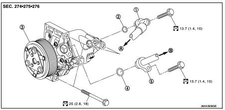
1. High-pressure flexible hose
2. O-ring
3. Compressor
4. O-ring
5. Low-pressure flexible hose
A. To condenser
B. To evaporator
 : N·m (kg-m, ft-lb)
DISASSEMBLY
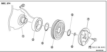
1. Compressor unit 2. Field coil 3. Snap ring 4. Pulley assembly 5. Snap ring 6. Shim 7. Clutch disc
 : N·m (kg-m, ft-lb)
Compressor : Removal and Installation
CAUTION:
Perform lubricant return operation before each refrigeration system disassembly.
However, if a large
amount of refrigerant or lubricant is detected, never perform lubricant return
operation. Refer to HA-
23, "Perform Lubricant Return Operation".
REMOVAL
1. Use a refrigerant collecting equipment (for HFC-134a) to discharge the refrigerant. Refer to HA-21, "Recycle Refrigerant".
2. Remove mounting bolts, and then disconnect low-pressure flexible hose and high-pressure flexible hose from the compressor.
CAUTION:
Cap or wrap the joint of the A/C piping and compressor with suitable material
such as vinyl tape to
avoid the entry of air.
3. Remove drive belt. Refer to EM-155, "Removal and Installation".
4. Disconnect compressor (magnet clutch) connector.
5. Remove mounting bolts, and then remove compressor form the vehicle.
INSTALLATION
Note the following items, and then install in the reverse order of removal.
CAUTION:
• Replace O-rings with new ones. Then apply compressor oil to them when
installing.
• Perform lubricant adjusting procedure before installing new compressor. Refer to HA-23, "Perform Lubricant Return Operation".
• Check for leakages when recharging refrigerant. Refer to HA-19, "Leak Test".
• Check tension of the drive belt after installing compressor. Refer to EM-154, "Checking"
.
Magnet clutch : Removal and Installation of Compressor Clutch
REMOVAL
Overhaul
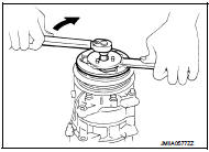
1. When removing center bolt, hold clutch disc with clutch disc
wrench (SST:KV99232340) (A).
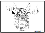
2. Remove clutch disc.
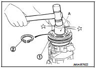
3. Remove snap ring using external snap ring pliers.
4. Position center pulley puller on the end of the drive shaft, and remove pulley assembly using any commercially available pulley puller.
To prevent pulley groove from being deformed, puller claws should be positioned into the edge of the pulley assembly.
5. Disconnect harness connector from compressor unit.
6. Remove snap ring using external snap ring pliers, and then remove field coil.
INSTALLATION
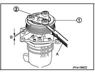
1. Install field coil (1).
Be sure to align the coil’s pin (2) with the hole in the compressor’s front head.
2. Install field coil harness clip.
3. Install pulley assembly (1) using pulley installer (SST:KV99106200) (A) and a hand press, and then install snap ring (2) using snap ring pliers.
4. Install clutch disc on drive shaft, together with original shim(s). Press clutch disc down by hand.
5. Tighten center bolt to the specified torque while fixing clutch disc not to rotate using a clutch disc wrench (SST:KV99232340).
After tightening the bolt, check that the pulley rotates smoothly.
Break-in Operation
When replacing compressor clutch assembly, always perform the break-in
operation, by engaging and disengaging
the clutch approximately 30-times. Break-in operation increases the level of
transmitted torque.
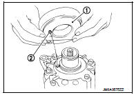
Inspection
CHECK DISC TO PULLEY CLEARANCE
Check the clearance (B) between pulley assembly (1) and clutch disc (2) along the entire periphery with a feeler gauge (A).
Clearance : Refer to HA-58, "Compressor".
Replace compressor if specified clearance is not obtained.

 Cooler pipe and hose
Exploded View
1. A/C unit assembly
2. O-ring
3. High-pressure pipe
4. Condenser
5. Low-pressure flexible hose
6. O-ring
7. Compressor
8. O-ring
9. High-pressure flexible hose
: Do no ...
Other materials:
P012A TC boost sensor
DTC Logic
DTC DETECTION LOGIC
Diagnosis Procedure
1.CHECK GROUND CONNECTIONS
1. Turn ignition switch OFF.
2. Check ground connection E38. Refer to Ground inspection in GI-44, "Circuit
Inspection".
Is the inspection result normal?
YES >> GO TO 2.
NO >> Repair or ...
Steering wheel turning force is heavy or light
Description
Steering wheel turning force is heavy or light.
Diagnosis Procedure
1.CHECK THE ILLUMINATION OF THE EPS WARNING LAMP
Check that the EPS warning lamp turns ON when ignition switch turns ON. Then,
EPS warning lamp turns
OFF after the engine is started.
Is the inspection result no ...
B260F Engine status
Description
BCM receives the engine status signal from ECM via CAN communication.
DTC Logic
DTC DETECTION LOGIC
NOTE:
• If DTC B260F is displayed with DTC U1000, first perform the trouble diagnosis
for DTC U1000. Refer to
BCS-83, "DTC Logic".
• If DTC B260F is displayed with DTC U ...
