Nissan Juke Service and Repair Manual : P012A TC boost sensor
DTC Logic
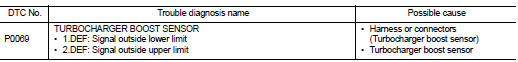
DTC DETECTION LOGIC
Diagnosis Procedure
1.CHECK GROUND CONNECTIONS
1. Turn ignition switch OFF.
2. Check ground connection E38. Refer to Ground inspection in GI-44, "Circuit Inspection".
Is the inspection result normal? YES >> GO TO 2.
NO >> Repair or replace ground connection.
2.CHECK TUBOCHARGER BOOST SENSOR SUPPLY CIRCUIT
1. Disconnect turbocharger boost sensor harness connector.
2. Turn ignition switch ON.
3. Check the voltage between turbocharger boost sensor connector and ground.
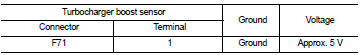
Is the inspection result normal? YES >> GO TO 3.
NO >> Repair open circuit or short to ground or short to power in harness or connectors.
3.CHECK TUBOCHARGER BOOST SENSOR GROUND CIRCUIT FOR OPEN AND SHORT
1. Turn ignition switch OFF.
2. Disconnect ECM harness connector.
3. Check the continuity between turbocharger boost sensor harness connector and ECM harness connector
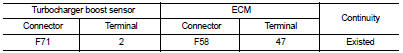
4. Also check harness for short to ground and short to power.
Is the inspection result normal? YES >> GO TO 4.
NO >> Repair open circuit or short to ground or short to power in harness or connectors.
4.CHECK TUBOCHARGER BOOST SENSOR INPUT SIGNAL CIRCUIT FOR OPEN AND SHORT
1. Check the continuity between turbocharger boost sensor harness connector and ECM harness connector.
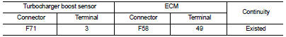
2. Also check harness for short to ground and short to power.
Is the inspection result normal?
YES >> GO TO 5.
NO >> Repair open circuit or short to ground or short to power in harness or connectors.
5.CHECK TUBOCHARGER BOOST SENSOR
Refer to EC-912, "Component Inspection".
Is the inspection result normal? YES >> GO TO 6.
NO >> Replace turbocharger boost sensor.
6.REPLACE ECM
1. Perform EC-879, "Work Procedure".
2. Perform EGR volume control valve closed position learning. Refer to EC-881, "Work Procedure".
>> INSPECTION END
Component Inspection
1.CHECK TURBOCHARGER BOOST SENSOR-I
1. Turn ignition switch OFF.
2. Remove turbocharger boost sensor with its harness connected.
3. Turn ignition switch ON.
4. Select ???DATA MONITOR??? mode with CONSULT-III.
5. Check ???BOOST PRESS??? and ???ATOMOS PRESS??? indication.
If the value is not very close to ???ATOMOS PRESS???, maximum pressure difference between ???ATOMOS PRESS??? and ???BOOST PRESS??? with the ignition switch ON (engine stop) = ?± 50 mbar? YES >> GO TO 2.
NO >> Replace turbocharger boost sensor.
2.CHECK TURBOCHARGER BOOST SENSOR-II
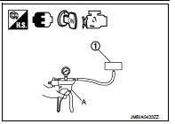
1. Use pump (A) to apply turbocharger boost sensor (1) as shown in the figure.
2. Apply a pressure of between 10 kPa (0.100 bar, 0.102 kg/cm2, 1.5 psi) - 13 kPa (0.130 bar, 0.133 kg/cm2, 1.9 psi) [maximum pressure to be applied: 13 kPa (0.130 bar, 0.133 kg/cm2, 1.9 psi)].
3. Select ???DATA MONITOR??? mode with CONSULT-III.
4. Check ???BOOST PRESS??? indication with that given by the vacuum pump.
If there is no discrepancy? YES >> INSPECTION END
NO >> Replace turbocharger boost sensor.
 P0120 TP sensor
DTC Logic
DTC DETECTION LOGIC
Diagnosis Procedure
1.CHECK GROUND CONNECTIONS
1. Turn ignition switch OFF and wait at least 20 seconds.
2. Check ground connection E38. Refer to Ground inspection ...
 P012B TC boost sensor
DTC Logic
DTC DETECTION LOGIC
Diagnosis Procedure
1.CHECK GROUND CONNECTIONS
1. Turn ignition switch OFF.
2. Check ground connection E38. Refer to Ground inspection in GI-44, "Circuit
In ...
Other materials:
Precaution
Service Notice or Precautions for Road Wheel
• Genuine NISSAN aluminum wheel is designed for each type of vehicle. Use it
on the specified vehicle only.
• Use Genuine NISSAN parts for the wheel nuts.
• Always use them after adjusting the wheel balance. For the balance weights,
use Genuine NIS ...
Microphone signal circuit
Description
Power is supplied from audio unit to microphone. The microphone transmits the
sound voice to the audio unit.
Diagnosis Procedure
1.CHECK CONTINUITY BETWEEN AUDIO UNIT AND MICROPHONE CIRCUIT
1. Turn ignition switch OFF.
2. Disconnect audio unit connector and microphone connector.
...
Condenser
Exploded View
Refer toINT-34, "Exploded View"
Removal and Installation
REMOVAL
1. Remove the back door lower finisher.
Refer to INT-35, "BACK DOOR LOWER FINISHER : Removal and Installation"
2. Remove bolt (A), and then remove condenser (1) from the vehicle
body.
INSTA ...
