Nissan Juke Service and Repair Manual : Camera image signal circuit
Description
• The NAVI control unit supplies power to the rear view camera when receiving a reverse signal.
• The rear view camera transmits camera images to the NAVI control unit when power is supplied from the NAVI control unit.
Diagnosis Procedure
1.CHECK CONTINUITY CAMERA POWER SUPPLY CIRCUIT
1. Turn ignition switch OFF.
2. Disconnect NAVI control unit connector and rear view camera connector.
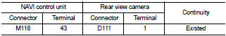
3. Check continuity between NAVI control unit harness connector and rear view camera harness connector.
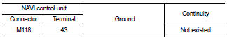
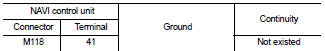
4. Check continuity between NAVI control unit harness connector and ground.
Is inspection result normal? YES >> GO TO 2.
NO >> Repair harness or connector.
2.CHECK VOLTAGE CAMERA POWER SUPPLY
1. Connect NAVI control unit connector and rear view camera connector.
2. Turn ignition switch ON.
3. Shift the selector lever to “R” position.
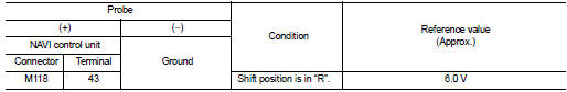
4. Check voltage between NAVI control unit harness connector and ground.
Is inspection result normal? YES >> GO TO 3.
NO >> Replace NAVI control unit. Refer to AV-84, "Removal and Installation".
3.CHECK CONTINUITY CAMERA IMAGE SIGNAL CIRCUIT
1. Turn ignition switch OFF.
2. Disconnect NAVI control unit connector and rear view camera connector.
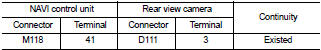
3. Check continuity between NAVI control unit harness connector and rear view camera harness connector.
4. Check continuity between NAVI control unit harness connector and ground.
Is inspection result normal? YES >> GO TO 4.
NO >> Repair harness or connector.
4.CHECK CAMERA IMAGE SIGNAL
1. Connect NAVI control unit connector and rear view camera connector.
2. Turn ignition switch ON.
3. Shift the selector lever to “R” position.
4. Check signal between NAVI control unit harness connector and ground.
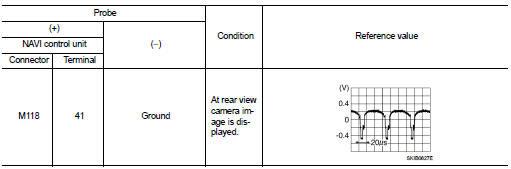
Is inspection result normal? YES >> Replace NAVI control unit. Refer to AV-84, "Removal and Installation".
NO >> Replace rear view camera. Refer to AV-92, "Removal and Installation".
 Microphone signal circuit
Description
Power is supplied from NAVI control unit to microphone. The microphone
transmits the sound voice to the
NAVI control unit.
Diagnosis Procedure
1.CHECK CONTINUITY BETWEEN NAVI CONTROL ...
 Steering switch signal A circuit
Description
Transmits the steering switch signal to NAVI control unit.
Diagnosis Procedure
1.CHECK STEERING SWITCH SIGNAL A CIRCUIT
1. Disconnect NAVI control unit connector and spiral cable conne ...
Other materials:
Back door opener system
System Diagram
System Description
BACK DOOR OPENER OPERATION
When back door opener switch is pressed, BCM operates back door opener
actuator.
NOTE:
Back door opener actuator is not for locking the back door. The function is only
to open the back door.
OPERATION CONDITION
If the foll ...
Rear fender cover
Exploded View
1. Rear fender cover
2. Rear fender
Removal and Installation
REMOVAL
Disengage rear fender cover fixing clips using remover tool (A), and
then remove rear fender cover.
CAUTION:
Apply protective tape (B) to the body side to protect from damage.
: Clip
INSTALLATION
Not ...
Hood
Exploded View
1. Hood assembly
2. Hood bumper rubber
3. Radiator core seal
4. Hood bumper rubber
5. Clamp
6. Hood hinge
7. Grommet
8. Hood support rod
: Clip
: Pawl
: Body grease
Hood assembly
HOOD ASSEMBLY : Removal and Installation
CAUTION:
• Operate with two workers, because ...
