Nissan Juke Service and Repair Manual : Microphone signal circuit
Description
Power is supplied from NAVI control unit to microphone. The microphone transmits the sound voice to the NAVI control unit.
Diagnosis Procedure
1.CHECK CONTINUITY BETWEEN NAVI CONTROL UNIT AND MICROPHONE CIRCUIT
1. Turn ignition switch OFF.
2. Disconnect NAVI control unit connector and microphone connector.
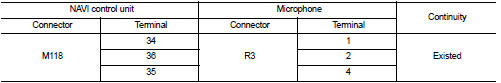
3. Check continuity between NAVI control unit harness connector and microphone harness connector.
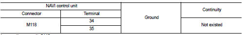
4. Check continuity between NAVI control unit harness connector and ground.
Is inspection result OK? YES >> GO TO 2.
NO >> Repair harness or connector.
2.CHECK VOLTAGE MICROPHONE VCC
1. Connect NAVI control unit connector.
2. Turn ignition switch ON.
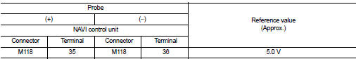
3. Check voltage between NAVI control unit harness connector and ground.
Is inspection result OK? YES >> GO TO 3.
NO >> Replace NAVI control unit. Refer to AV-84, "Removal and Installation".
3.CHECK MICROPHONE SIGNAL
1. Turn ignition switch OFF.
2. Connect microphone connector.
3. Turn ignition switch ON.
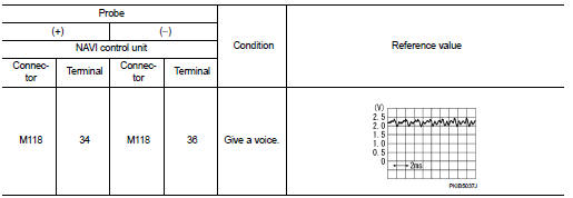
4. Check signal between NAVI control unit harness connector.
Is inspection result OK? YES >> Replace NAVI control unit. Refer to AV-84, "Removal and Installation".
NO >> Replace microphone. Refer to AV-90, "Removal and Installation".
 Power supply and ground circuit
Navi control unit
NAVI CONTROL UNIT : Diagnosis Procedure
1.CHECK FUSE
Check for blown fuses.
Is inspection result OK?
YES >> GO TO 2.
NO >> Be sure to eliminate cause of malfunc ...
 Camera image signal circuit
Description
• The NAVI control unit supplies power to the rear view camera when receiving
a reverse signal.
• The rear view camera transmits camera images to the NAVI control unit when
power is ...
Other materials:
Parking brake control
Exploded View
2WD
1. Parking brake lever assembly
2. Adjusting nut
3. Parking brake switch
4. Front cable
5. Rear cable (LH)
6. Rear cable (RH)
: Apply multi-purpose grease.
: N·m (kg-m, ft-lb)
: N·m (kg-m, in-lb)
: Always replace after every
disassembly.
4WD
1. Parking brake ...
System setting
Temperature Setting Trimmer
DESCRIPTION
If the temperature felt by the customer is different from the air flow
temperature controlled by the temperature
setting, the A/C auto amp. control temperature can be adjusted to compensate for
the temperature setting.
HOW TO SET
With CONSULT-III
P ...
Excessive operation frequency
Description
ABS function and EBD function operates in excessive operation frequency.
Diagnosis Procedure
1.CHECK BRAKING FORCE
Check brake force using a brake tester.
Is the inspection result normal?
YES >> GO TO 2.
NO >> Check brake system.
2.CHECK FRONT AND REAR AXLE
Che ...
