Nissan Juke Service and Repair Manual : Steering switch signal A circuit
Description
Transmits the steering switch signal to NAVI control unit.
Diagnosis Procedure
1.CHECK STEERING SWITCH SIGNAL A CIRCUIT
1. Disconnect NAVI control unit connector and spiral cable connector.
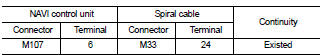
2. Check continuity between NAVI control unit harness connector and spiral cable harness connector.
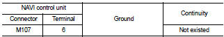
3. Check continuity between NAVI control unit harness connector and ground.
Is the inspection result normal? YES >> GO TO 2.
NO >> Repair harness or connector.
2.CHECK SPIRAL CABLE
Check spiral cable.
Is the inspection result normal? YES >> GO TO 3.
NO >> Replace spiral cable. Refer to SR-16, "Exploded View".
3.CHECK NAVI CONTROL UNIT VOLTAGE
1. Connect NAVI control unit connector and spiral cable connector.
2. Turn ignition switch ON.
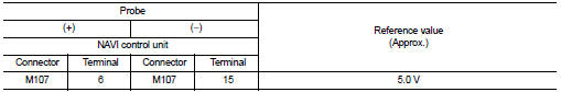
3. Check voltage between NAVI control unit harness connector.
Is the inspection result normal? YES >> GO TO 4.
NO >> Replace NAVI control unit. Refer to AV-84, "Removal and Installation".
4.CHECK STEERING SWITCH
1. Turn ignition switch OFF.
2. Check steering switch. Refer to AV-72, "Component Inspection".
Is the inspection result normal? YES >> INSPECTION END
NO >> Replace steering switch. Refer to AV-91, "Exploded View".
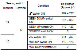
Component Inspection
Measure the resistance between the steering switch connector
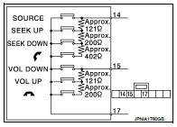
Standard
 Camera image signal circuit
Description
• The NAVI control unit supplies power to the rear view camera when receiving
a reverse signal.
• The rear view camera transmits camera images to the NAVI control unit when
power is ...
 Steering switch signal B circuit
Description
Transmits the steering switch signal to NAVI control unit.
Diagnosis Procedure
1.CHECK STEERING SWITCH SIGNAL B CIRCUIT
1. Disconnect NAVI control unit connector and spiral cable conne ...
Other materials:
Blower fan on signal
Component Function Check
1.CHECK BLOWER FAN ON SIGNAL
With CONSULT-III
1. Turn ignition switch ON.
2. Select “AIR CONDITIONER” of “BCM” using CONSULT-III.
3. Select “FAN ON SIG” in “DATA MONITOR” mode.
4. Check blower fan ON signal when the fan control dial is operated.
Is the inspection re ...
Engine control system symptoms
Symptom Table
SYSTEM — BASIC ENGINE CONTROL SYSTEM
1 - 6: The numbers refer to the order of inspection.
(continued on next table)
SYSTEM — ENGINE MECHANICAL & OTHER
1 - 6: The numbers refer to the order of inspection ...
B2192 ID discord, IMMU-ECM
DTC Logic
DTC DETECTION LOGIC
DTC CONFIRMATION PROCEDURE
1.PERFORM DTC CONFIRMATION PROCEDURE
1. Turn ignition switch ON.
2. Check DTC in “Self Diagnostic Result” mode of “BCM” using CONSULT-III.
Is DTC detected?
YES >> Refer to SEC-204, "Diagnosis Procedure".
NO >&g ...
