Nissan Juke Service and Repair Manual : B terminal circuit
Description
The “B” terminal is constantly supplied with battery power.
Diagnosis Procedure
CAUTION:
Perform diagnosis under the condition that engine cannot start by the following
procedure.
1. Remove fuel pump fuse.
2. Crank or start the engine (where possible) until the fuel pressure is released.
1.INSPECTION START
Check which type of engine the vehicle is equipped with.
Which type of engine? HR16DE engine models>>GO TO 4.
Except HR16DE engine models>>GO TO 2.
2.CHECK FUSIBLE LINK
Check that the following fusible link is not blown.
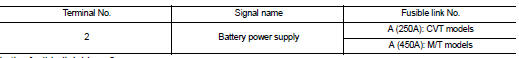
Is the fusible link blown? YES >> Replace the blown fusible link after repairing the affected circuit if a fusible link is blown.
NO >> GO TO 3.
3.CHECK “B” TERMINAL CIRCUIT
1. Turn ignition switch OFF.
2. Check that starter motor “B” terminal connection is clean and tight.
3. Check voltage between starter motor “B” terminal and ground.
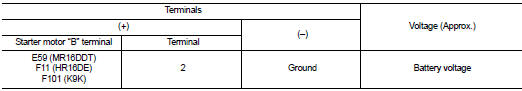
Is the inspection result normal? YES >> GO TO 4.
NO >> Check harness between battery and starter motor for open circuit.
4.CHECK BATTERY CABLE CONNECTION STATUS (VOLTAGE DROP TEST)
1. Shift selector lever to “P” or “N” position. (CVT models) Keep depressing clutch pedal fully. (M/T models with Intelligent Key system) 2. Check voltage between battery positive terminal and starter motor “B” terminal.
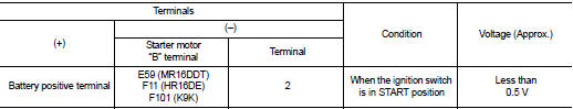
Is the inspection result normal? YES >> GO TO 5.
NO >> Check harness between the battery and the starter motor for poor continuity.
5.CHECK GROUND CIRCUIT STATUS (VOLTAGE DROP TEST)
1. Shift selector lever to “P” or “N” position. (CVT models) Keep depressing clutch pedal fully. (M/T models with Intelligent Key system) 2. Check voltage between starter motor case and battery negative terminal.
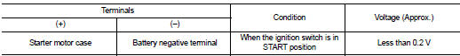
Is the inspection result normal? YES >> “B” terminal circuit is OK. Further inspection is necessary. Refer to STR-14, "Work Flow".
NO >> Check the starter motor case and ground for poor continuity.

 S terminal circuit
Description
The starter motor magnetic switch is supplied with power when the ignition
switch is turned to the START position
while the selector lever is in the P or N position for CVT models or t ...
Other materials:
System
4WD system : System Diagram
INPUT/OUTPUT SIGNAL
It transmits/receives each signal from the following 4WD control module via
CAN communication line.
4WD system : System Description
• 4WD mode is selectable among 2WD, 4WD-V, and 4WD by operating the 4WD mode
switch.
• When judging drivi ...
Diagnosis system (A/C auto AMP.)
Description
Air conditioning system performs self-diagnosis, operation check, function
diagnosis, and various settings
using diagnosis function of each control unit.
CONSULT-III Function
CONSULT-III performs the following functions via CAN communication with A/C
auto amp.
NOTE:
Diagnos ...
Front seat-mounted side-impact supplemental air bag and roof-mounted curtain
side-impact supplemental air bag systems
The side air bags are located in the outside of the seatback of the front seats.
The curtain air bags are located in the side roof rails. All of the information,
cautions and warnings in this manual still apply and must be followed.
The side air bags and curtain air bags are designed to infla ...
