Nissan Juke Service and Repair Manual : System
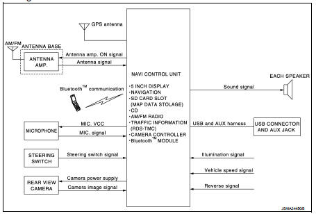
System Diagram
System Description
Refer to Owner’s Manual for navigation and audio system operating instructions.
Audio function and display are built into NAVI control unit.
This navigation has the following functions.
• All of European Map including UK postcode on SD-card.
• Full support for playback of music from iPod® and USB device.
• High resolution color 5 inch display with touch panel function.
• FM/AM twin digital tuner.
• USB mass storage connection.
• Bluetooth™ audio streaming.
• RDS-TMC.
• Hands-free phone system.
• Anti-theft system.
iPod® is a trademark of Apple inc., registered in the U.S. and other countries.
NAVIGATION SYSTEM FUNCTION
Description
• The navigation system can be operated by control panel of the NAVI control
unit and display (touch panel) of
the NAVI control unit.
• Guide sound during the operation of the navigation system is output from NAVI control unit to front speaker.
• NAVI control unit calculates the vehicle location based on the signals from GYRO (angle speed sensor), vehicle sensor, and GPS satellite, as well as the map data from map SD-card. It is displayed on display of the NAVI control unit.
POSITION DETECTION PRINCIPLE
The navigation system periodically calculates the vehicle's current position
according to the following three
signals:
• Travel distance of the vehicle as determined by the vehicle speed sensor
• Turning angle of the vehicle as determined by the gyroscope (angular velocity
sensor)
• Direction of vehicle travel as determined by the GPS antenna (GPS information)
The current position of the vehicle is then identified by comparing the calculated vehicle position with map data read from the map SD-card (map-matching), and indicated on the screen as a vehicle mark. More accurate data is judged and used by comparing vehicle position detection results found by the GPS with the result by map-matching.
The current vehicle position will be calculated by detecting the distance the vehicle moved from the previous calculation point and its direction.
• Travel distance
Travel distance calculations are based on the vehicle speed sensor
input signal. Therefore, the calculation may become incorrect
as the tires wear down. To prevent this, an automatic distance correction
function has been adopted.
• Travel direction
Change in the travel direction of the vehicle is calculated by a gyroscope
(angular velocity sensor) and a GPS antenna (GPS information).
They have both advantages and disadvantages.
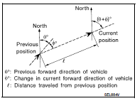
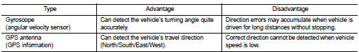
More accurate traveling direction is detected because priorities are set for the signals from these two devices according to the situation.
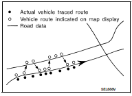
MAP-MATCHING
Map-matching compares a current location detected by the method in the “Location Detection Principle” with a road map data from map SD-card.
NOTE
:
The road map data is based on data stored in the map SD-card.
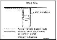
The vehicle position may not be corrected under the following circumstances and after driving for a certain time when GPS information is difficult to receive. In this case, the vehicle mark on the display must be corrected manually.
• In map-matching, alternative routes to reach the destination will be shown and prioritized, after the road on which the vehicle is currently driven has been judged and the vehicle mark has been repositioned.
Alternative routes will be shown in different order of priority, and the incorrect road can be avoided if there is an error in distance and/or direction.
They are of the same priority if two roads are running in parallel.
Therefore, the vehicle mark may appear on either of them alternately, depending on maneuvering of the steering wheel and configuration of the road.
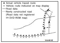
• Map-matching does not function correctly when a road on which the vehicle is driving is new and not recorded in the map SD-card, or when road pattern stored in the map data and the actual road pattern are different due to repair.
The map-matching function may find another road and position the vehicle mark on it when driving on a road not present in the map.
Then, the vehicle mark may change to it when the correct road is detected.
• Effective range for comparing the vehicle position and travel direction calculated by the distance and direction with the road data read from the map SD-card is limited. Therefore, correction by map-matching is not possible when there is an excessive gap between current vehicle position and the position on the map.
GPS (Global Positioning System) GPS (Global Positioning System) is developed for and is controlled by the US Department of Defense. The system utilizes GPS satellites (NAVSTAR), transmitting out radio waves while flying on an orbit around the earth at an altitude of approximately 21,000 km (13,049 mile).
The receiver calculates the travel position in three dimensions (latitude/ longitude/altitude) according to the time lag of the radio waves that four or more GPS satellites transmit (three-dimensional positioning).
The GPS receiver calculates the travel position in two dimensions (latitude/longitude) with the previous altitude data if the GPS receiver receives only three radio waves (two-dimensional positioning).
GPS position correction is not performed while stopping the vehicle.
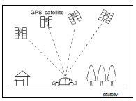
Accuracy of the GPS will deteriorate under the following conditions: • In two-dimensional positioning, GPS accuracy will deteriorate when altitude of the vehicle position changes.
• The position of GPS satellite affects GPS detection precision. The position detection may not be precisely performed.
• The position detection is not performed if GPS receiver does not receive radio waves from GPS satellites.
(Inside a tunnel, parking in a building, under an elevated highway etc.) GPS receiver may not receive radio waves from GPS satellites if any object is placed on the GPS antenna.
NOTE
:
• The detection result has an error of approximately 10 m (32.81 ft) even with a
high-precision three dimensional
positioning.
• There may be cases when the accuracy is lowered and radio waves are stopped intentionally because the GPS satellite signal is controlled by the US trace control center.
TRAFFIC INFORMATION (RDS-TMC) FUNCTION
The traffic information broadcast can avoid delays due to traffic incidents.
Traffic jams, roadwork, closed roads around current location, etc. are represented graphically on the map by icons depicting the nature of the event. Incidents on the route are automatically noticed when they are approached.
The traffic information feature gives the driver the opportunity to forecast traffic incidents, determine how serious they are and, via the guidance mode, allows to detour around traffic problems.
The navigation system receives traffic information from best available sources and enables the RDS-TMC (Radio Data System-Traffic Message Channel) to inform and guide the driver.
• Traffic information function is built into NAVI control unit.
• Traffic information is received by radio antenna, next it is amplified by antenna amp., and finally it is input to NAVI control unit. (Antenna amp. is built into antenna base.)
AUXILIARY INPUT FUNCTION
• Sound can be output from an external device by connecting a device with USB connector and AUX jack.
• AUX sound signals are transmitted to each speaker through NAVI control unit.
REAR VIEW MONITOR FUNCTION
Camera Image Operation Principle • The NAVI control unit supplies power to the rear view camera when receiving a reverse signal.
• The rear view camera transmits camera images to the NAVI control unit when power is supplied from the NAVI control unit.
• The NAVI control unit combines a warning message and fixed guide lines with an image received from the rear view camera to display a rear view camera image on the screen.
USB CONNECTION FUNCTION
• iPod® or music files in USB memory can be played.
• Sound signals are transmitted from USB connector and AUX jack to the NAVI control unit and to each speaker.
• iPod® is recharged when connected to USB connector and AUX jack.
iPod® is a trademark of Apple inc., registered in the U.S. and other countries.
NOTE
:
Use the enclosed USB harness when connecting iPod® to USB connector and AUX
jack.
SPEED SENSITIVE VOLUME SYSTEM
• Volume level of this system gone up and down automatically in proportion to the vehicle speed.
• The control level can be selected by the customer.
HANDS-FREE PHONE SYSTEM
• Hands-free communication can be operated by connecting using Bluetooth™ communication with cellular phone.
• Operation is performed by steering switch.
• Guide sound that is heard during operation is output from NAVI control unit to front speaker.
ANTI-THEFT SYSTEM
• The NAVI control unit is equipped with the anti-theft system.
• The NAVI control unit operates after authenticating a fixed four-digit anti-theft code.
• After removing the battery of the NAVI control unit, the authentication of the anti-theft code is required.
• If the anti-theft code cannot be authenticated, the NAVI control unit performs control as follows:
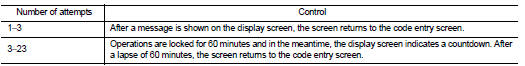
CAUTION:
• 24 or more: Operations are locked and a message is shown on the display. Code
numbers cannot
be input.
• The number of failed attempts is not reset and accumulated after any authentication
.
• The operating procedure: refer to AV-65, "Work Procedure".
 Component parts
Component Parts Location
1. Front door speaker LH
2. Rear door speaker LH
3. Rear view camera
4. Rear door speaker RH
5. Antenna rod
6. Antenna base (antenna amp.)
7. Front door speaker R ...
 Diagnosis system (navi control unit)
Diagnosis Description
On-Board Diagnosis Item
• On-board diagnosis is performed in service test mode.
• On-board diagnosis checks if the system operates normally.
Service test mode
METH ...
Other materials:
Inside key antenna
Instrument center
INSTRUMENT CENTER : Removal and Installation
REMOVAL
1. Remove the multi display unit. Refer to AV-125, "Removal and
Installation".
2. Remove the inside key antenna (instrument center) (1) mounting
clip (A), and then remove inside key antenna (instrument
center).
...
Door lock status indicator
Component Function Check
1.CHECK FUNCTION
1. Select “DOOR LOCK” of “BCM” using CONSULT-III.
2. Select “DOOR LOCK IND” in “ACTIVE TEST” mode.
3. Check that the function operates normally according to the following
conditions.
Is the inspection result normal?
YES >> Doo ...
Rear window defogger system
Wiring Diagram - DEFOGGER CONTROL SYSTEM -
For connector terminal arrangements, harness layouts, and alphabets in a
(option abbreviation; if not
described in wiring diagram), refer to GI-12, "Connector Information/Explanation
of Option Abbreviation".
...
