Nissan Juke Service and Repair Manual : Removal and Installation
REMOVAL
1. Remove engine assembly. Refer to EM-55, "2WD : Exploded View" (2WD) , EM-59, "4WD : Exploded View" (4WD).
2. Remove oil pan (lower). Refer to EM-41, "Removal and Installation".
3. Remove front cover, and other related parts. Refer to EM-67, "Exploded View".
4. Remove oil pump sprocket with the following procedure: • Add matching mark if necessary for easier installation.
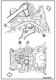
a. Push oil pump drive chain tensioner (1) in the direction show in the figure (A).
b. Insert a stopper pin (A) into the body hole (B).
c. Remove oil pump chain tensioner.
• When the holes on lever and tensioner body cannot be aligned, align these holes by slightly moving the oil pump chain tensioner slack guide.
![d. Hold the WAF part of oil pump shaft [WAF: 10 mm (0.39 in)] (A),](images/books/335/8/index.46.jpg)
d. Hold the WAF part of oil pump shaft [WAF: 10 mm (0.39 in)] (A), and then loosen the oil pump sprocket bolt and remove it.
1 : Oil pan (upper)
 : Engine front
CAUTION:
• Secure the oil pump shaft with the WAF part.
• Never loosen the oil pump sprocket bolt by tightening the oil pump drive chain.
e. Remove oil pump sprocket.
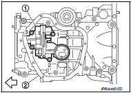
5. Remove oil pump.
• Loosen bolts in reverse order as shown in the figure.
1 : Oil pump
2 : Oil pan (upper)
: Engine front
INSTALLATION
Note the following, and install in the reverse order of removal.
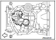
Oil Pump
• Tighten bolts in numerical order as shown in the figure.
1 : Oil pump
2 : Oil pan (upper)
: Engine front
 Exploded View
1. O-ring
2. Oil pan (upper)
3. Oil level gauge guide
4. O-ring
5. Oil level gauge
6. Oil pump drive chain
7. Crankshaft sprocket
8. Oil pump sprocket
9. Oil pump chain tensioner
10. ...
 Inspection
INSPECTION AFTER INSTALLATION
1. Check the engine oil level. Refer to LU-8, "Inspection".
2. Start the engine, and check that there is no leakage of engine oil.
3. Stop the engine and wai ...
Other materials:
Front drive shaft boot
Exploded View
LEFT SIDE
1. Circular clip
2. Dust shield
3. Housing assembly
4. Boot band
5. Boot
6. Damper band
7. Dynamic damper
8. Circular clip
9. Joint sub-assembly
: Wheel side
: Fill NISSAN Genuine grease or
equivalent.
: Always replace after every
disassembly.
RIGHT ...
Precaution Necessary for Steering Wheel Rotation after Battery Disconnect
NOTE:
• Before removing and installing any control units, first turn the ignition
switch to the LOCK position, then disconnect
both battery cables.
• After finishing work, confirm that all control unit connectors are connected
properly, then re-connect both
battery cables.
• Always us ...
LAN System can system (type 11)
DTC/CIRCUIT DIAGNOSIS
Main line between IPDM-E and DLC circuit
Diagnosis Procedure
1.CHECK CONNECTOR
1. Turn the ignition switch OFF.
2. Disconnect the battery cable from the negative terminal.
3. Check the following terminals and connectors for damage, bend and loose
connection (connector s ...
