
Nissan Juke Owners Manual : Continuously Variable Transmission (CVT)
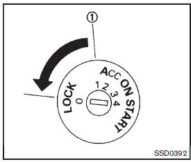
The ignition lock is designed so that the ignition switch cannot be turned to the LOCK position until the shift lever is moved to the P (Park) position.
• When turning the ignition switch to the LOCK position, make sure that the shift lever is in the P (Park) position.
• When removing the key from the ignition switch, make sure that the shift lever is in the P (Park) position.
When the ignition switch cannot be turned to the LOCK position:
1. Move the shift lever to the P (Park) position.
2. Turn the ignition switch slightly in the ON direction.
3. Turn the ignition switch to the LOCK position.
4. Remove the key.
If the ignition switch is turned to the LOCK position, the shift lever cannot be moved from the P (Park) position. The shift lever can be moved if the ignition switch is in the ON position with the foot brake pedal depressed.
There is an OFF position 1 between the LOCK and ACC positions, although it is not marked on the ignition switch.
 Ignition switch (models without Intelligent Key system)
WARNING
Never remove or turn the key to the LOCK position while driving. This may
cause the driver to lose control of the vehicle and could result in serious vehicle
damage or personal injury. ...
 Manual Transmission (MT)
The ignition switch includes a device that helps prevent accidental removal of
the key while driving.
The key can only be removed when the ignition switch is in the LOCK position.
To turn the ig ...
Other materials:
B20A0 cranking request circuit
DTC Logic
DTC DETECTION LOGIC
NOTE:
If DTC B20A0 is displayed with DTC U1000, first perform the trouble diagnosis
for DTC U1000. Refer to PCS-
30, "DTC Logic".
DTC CONFIRMATION PROCEDURE
1.PERFORM DTC CONFIRMATION PROCEDURE
1. Perform DTC CONFIRMATION PROCEDURE for DTC P1650. Re ...
Rear power window switch
Component Function Check
1. CHECK REAR POWER WINDOW SWITCH FUNCTION
Check rear power window motor operation with rear power window switch.
Is the inspection result normal?
YES >> INSPECTION END
NO >> Refer to PWC-24, "Diagnosis Procedure".
Diagnosis Procedure
1.CHECK R ...
Child safety
WARNING
Never allow children to play with the seat belts in your Nissan Leaf. Most seating positions are equipped with Automatic Locking Retractor (ALR) mode seat belts designed for child restraint installation. If a seat belt becomes wrapped around a child's neck while the ALR mode is engaged, ...
