Nissan Juke Service and Repair Manual : Wiring diagram
Engine control system
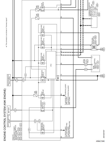
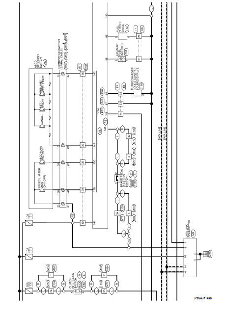
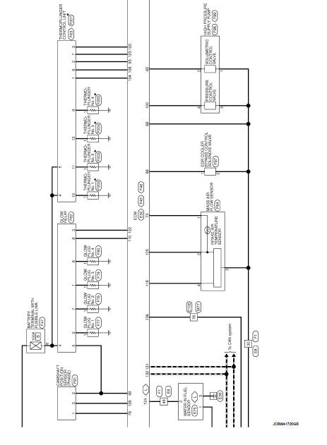
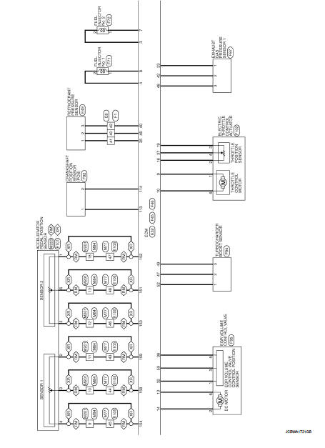
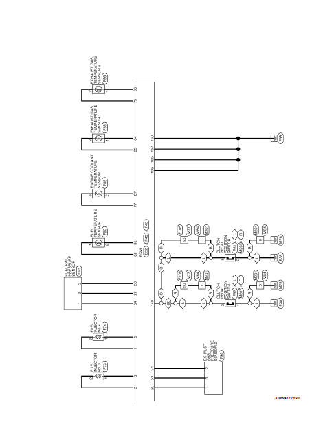
Wiring Diagram
For connector terminal arrangements, harness layouts, and alphabets in a
 (option abbreviation; if not
described in wiring diagram), refer to GI-12, "Connector Information/Explanation
of Option Abbreviation".
 ECU diagnosis information
ECM
Reference Value
TERMINAL LAYOUT
PHYSICAL VALUES
NOTE:
• ECM is located in the engine room left side near battery.
• When disconnecting ECM harness connector (1), loosen (B) it with
levers ...
 Basic inspection
...
Other materials:
Parts Requiring Angle Tightening
• Use the angle wrench [SST: KV10112100] for the final tightening of the
following engine parts:
- Cylinder head bolts
- Lower cylinder block bolts
- Connecting rod cap bolts
- Crankshaft pulley bolt (No the angle wrench is required as bolt flange is
provided with notches for angle
tighteni ...
C1143 steering angle sensor
DTC Logic
DTC DETECTION LOGIC
DTC CONFIRMATION PROCEDURE
1.PRECONDITIONING
If “DTC CONFIRMATION PROCEDURE” has been previously conducted, always turn
ignition switch OFF and
wait at least 10 seconds before conducting the next test.
>> GO TO 2.
2.CHECK DTC DETECTION
With CONSULT ...
Clutch pedal position switch
Component Function Check
1.CHECK FOR CLUTCH PEDAL POSITION SWITCH FUNCTION
1. Turn ignition switch ON.
2. Check the voltage between ECM harness connector and ground.
Is the inspection result normal?
YES >> INSPECTION END.
NO >> Proceed to EC-427, "Diagnosis Procedure" ...
