Nissan Juke Service and Repair Manual : ECU diagnosis information
ECM
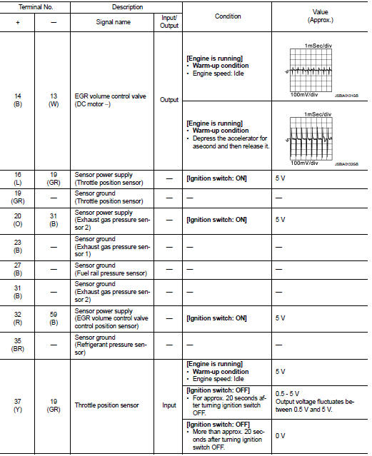
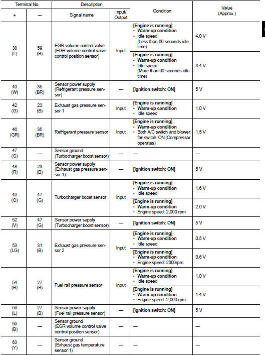
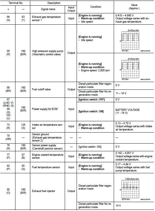
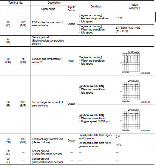
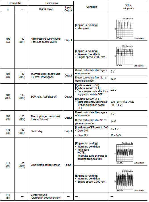
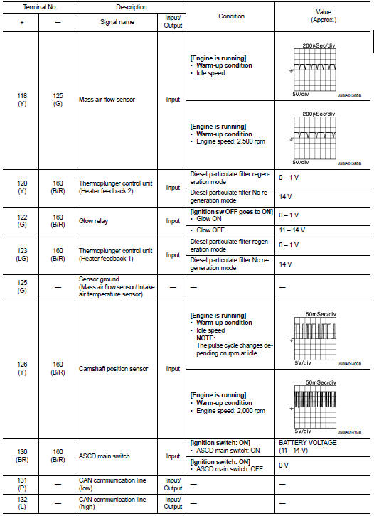
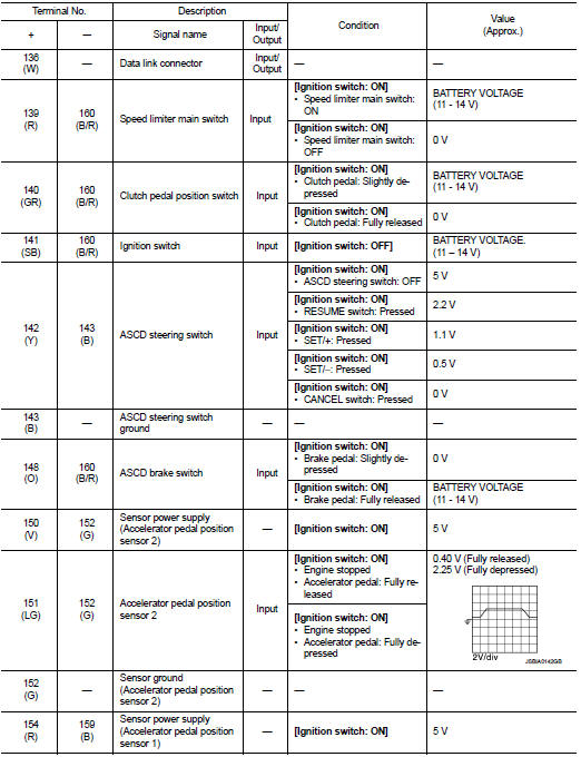
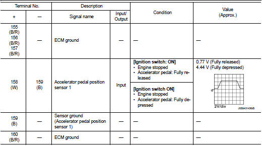
Reference Value
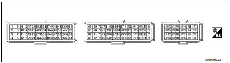
TERMINAL LAYOUT
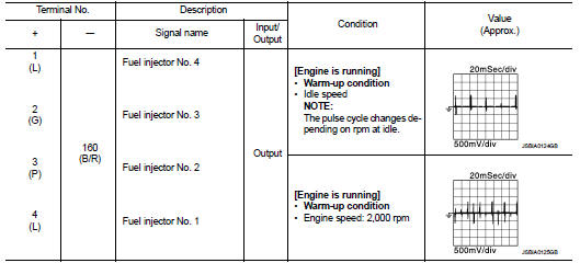
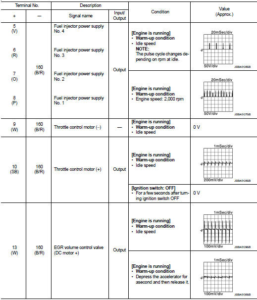
PHYSICAL VALUES
NOTE
:
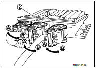
• ECM is located in the engine room left side near battery.
• When disconnecting ECM harness connector (1), loosen (B) it with levers as far as they will go as shown in the figure.
2 : ECM
A : Fasten
• Pulse signal is measured by CONSULT-III.
DTC Index
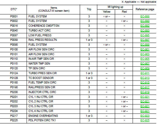
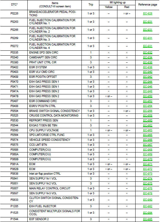
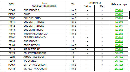
*: This number is prescribed by ISO 15031-6.
 On board diagnostic (OBD) system
Diagnosis Description
The ECM controls the display on the instrument panel of certain information
relating to the operation of the
engine.
Four functions are involved here: The OBD malfunction ...
 Wiring diagram
Engine control system
Wiring Diagram
For connector terminal arrangements, harness layouts, and alphabets in a
(option abbreviation; if not
described in wiring diagram), refer to GI-12, "Conne ...
Other materials:
Precaution Necessary for Steering Wheel Rotation after Battery Disconnect
NOTE:
• Before removing and installing any control units, first turn the ignition
switch to the LOCK position, then disconnect
both battery cables.
• After finishing work, confirm that all control unit connectors are connected
properly, then re-connect both
battery cables.
• Always use CONS ...
Anti-pinch system does not operate normally (driver side)
Diagnosis Procedure
1.CHECK POWER WINDOW AUTO OPERATION
Check AUTO operation when anti-pinch function does not operate.
Is the inspection result normal?
YES >> GO TO 2.
NO >> Refer to PWC-41, "Diagnosis Procedure".
2.CONFIRM THE OPERATION
Confirm the operation agai ...
G sensor calibration
Description
TCM stores calibration data (inherent characteristic value) of G sensor to
provide accurate control. Therefore,
it is required to perform calibration of G sensor after the following work is
performed.
• Removal/installation or replacement of G sensor
• Replacement of TCM
Proce ...
