Nissan Juke Service and Repair Manual : Wiring diagram
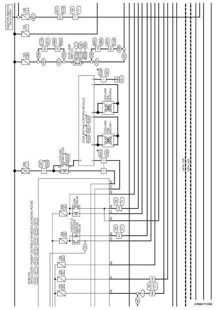
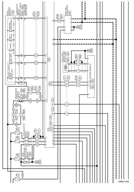
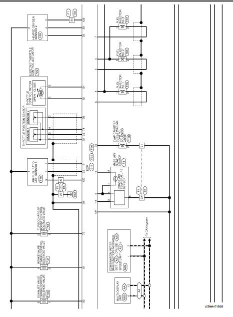
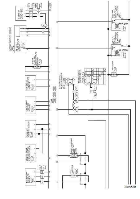
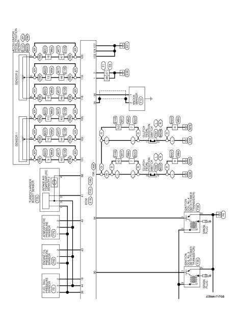
Engine control system
For connector terminal arrangements, harness layouts, and alphabets in a
 (option abbreviation; if not
described in wiring diagram), refer to GI-12, "Connector Information/Explanation
of Option Abbreviation".

 Test Value and Test Limit
The following is the information specified in Service $06 of ISO 15031-5.
The test value is a parameter used to determine whether a system/circuit
diagnostic test is OK or NG while
being monitor ...
 Basic inspection
...
Other materials:
Engine does not start or starts with difficulty
Description
CHART 2: ENGINE DOES NOT START OR STARTS WITH DIFFICULTY
Diagnosis Procedure
1.CHECK FUEL
Check that the fuel reservoir is correctly filled and with the right fuel.
>> GO TO 2.
2.CHECK BATTERY
Check the battery. Refer to PG-124, "Removal and Installation".
I ...
Precaution Necessary for Steering Wheel Rotation after Battery Disconnect
NOTE:
• Before removing and installing any control units, first turn the ignition
switch to the LOCK position, then disconnect
both battery cables.
• After finishing work, confirm that all control unit connectors are connected
properly, then re-connect both
battery cables.
• Always use CONS ...
Control valve
Exploded View
COMPONENT PARTS LOCATION
1. Transaxle assembly
2. Control valve
3. Bracket
4. O-ring
5. Oil strainer assembly
6. Magnet
7. Drain plug gasket
8. Drain plug
9. Oil pan mounting bolt
10. Oil pan
11. Oil pan gasket
12. Lock nut
13. Washer
14. Manual plate
15. Co ...
