Nissan Juke Service and Repair Manual : Wiring diagram
CAN SYSTEM
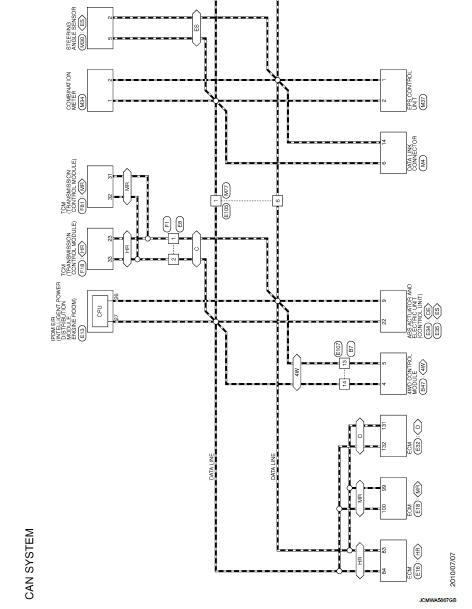
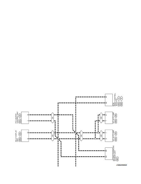
Wiring Diagram
For connector terminal arrangements, harness layouts, and alphabets in a
 (option abbreviation; if not
described in wiring diagram), refer to GI-12, "Connector Information/Explanation
of Option Abbreviation".
 System
Can communication system
CAN COMMUNICATION SYSTEM : System Diagram
CAN COMMUNICATION SYSTEM : System Description
Description
• CAN (Controller Area Network) is a serial communication line for re ...
 Basic inspection
DIAGNOSIS AND REPAIR WORKFLOW
Interview Sheet
NOTE:
Refer to LAN-17, "Trouble Diagnosis Procedure" for how to use interview sheet.
...
Other materials:
The oil pressure warning lamp does not turn on
Description
The oil pressure warning lamp stays off when the ignition switch is turned
ON.
Diagnosis Procedure
1.CHECK OIL PRESSURE WARNING LAMP
Perform auto active test. Refer to PCS-12, "Diagnosis Description" (with
I-KEY) or PCS-43, "Diagnosis
Description" (without I- ...
P0744 torque converter
DTC Logic
DTC DETECTION LOGIC
DTC CONFIRMATION PROCEDURE
CAUTION:
Be careful of the driving speed.
1.PREPARATION BEFORE OPERATION 1
If another "DTC CONFIRMATION PROCEDURE" occurs just before, turn ignition
switch OFF and wait for at
least 10 seconds, then perform the next test.
...
Blower motor
Diagnosis Procedure
1.CHECK SYMPTOM
Check symptom (A or B).
Which symptom is detected?
A >>GO TO 2.
B >>GO TO 7.
2.CHECK FUSE
1. Turn ignition switch OFF.
2. Check 15A fuses (Nos. 14 and 16, located in fuse block (J/B)].
NOTE:
Refer to PG-22, "Fuse, Connector and T ...
