Nissan Juke Service and Repair Manual : System
Can communication system
CAN COMMUNICATION SYSTEM : System Diagram
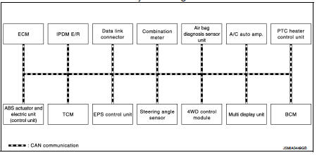
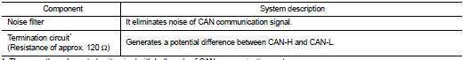
CAN COMMUNICATION SYSTEM : System Description
Description
• CAN (Controller Area Network) is a serial communication line for real time
application. It is an on-vehicle
multiplex communication line with high data communication speed and excellent
error detection ability. Many
electronic control units are equipped onto a vehicle, and each control unit
shares information and links with
other control units during operation (not independent). In CAN communication,
control units are connected
with 2 communication lines (CAN-H line, CAN-L line) allowing a high rate of
information transmission with
less wiring. Each control unit transmits/receives data but selectively reads
required data only.
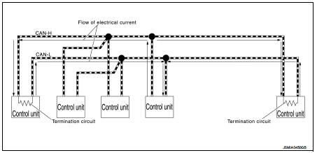
• Termination circuits (resistors) are connected across the CAN communication system. When transmitting a CAN communication signal, each control unit passes a current to the CAN-H line and the current returns to the CAN-L line. The current flows separately into the termination circuits connected across the CAN communication system and the termination circuits drop voltage to generate a potential difference between the CAN-H line and the CAN-L line. The system produces digital signals for signal communications, by using the potential difference.
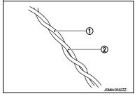
CAN Communication Line The CAN communication line is a twisted pair wire consisting of strands of CAN-L (1) and CAN-L (2) and has noise immunity.
NOTE
:
The CAN communication system has the characteristics of noise-resistant because
this system produces digital
signals by using the potential difference between the CAN-H line and the CAN-L
line and has the twisted
pair wire structure.
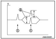
Since the CAN-H line and the CAN-L line are always adjacent to each other, the same degree of noise occurs, respectively, when a noise (1) occurs. Although the noise changes the voltage, the potential difference (2) between the CAN-H line and the CAN-L line is insensitive to noise. Therefore, noise-resistant signals can be obtained.
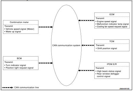
CAN Signal Communications Each control unit of the CAN communication system transmits signals through the CAN communication control circuit included in the control unit and receives only necessary signals from each control unit to perform various kinds of control.
• Example: Transmitted signals
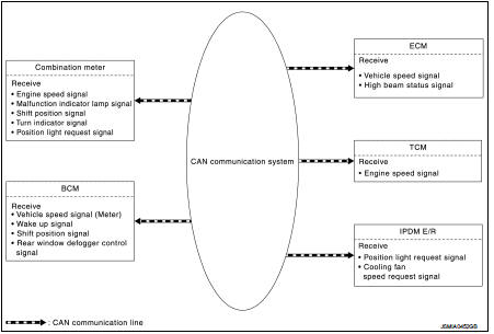
• Example: Received signals
NOTE
:
The above signal names and signal communications are provided for reference
purposes. For CAN communications
signals of this vehicle, refer to LAN-31, "CAN COMMUNICATION SYSTEM : CAN
Communication
Signal Chart".
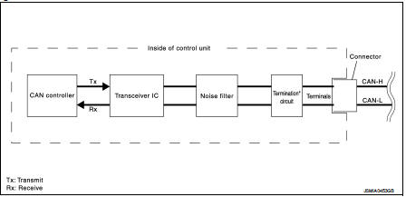
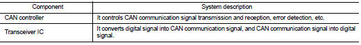
Can communication system : CAN Communication Control Circuit
CAN communication control circuit is incorporated into the control unit and transmits/receives CAN communication signals.
*: These are the only control units wired with both ends of CAN communication system
Can communication system : CAN System Specification Chart
Determine CAN system type from the following specification chart.
NOTE
:
Refer to LAN-17, "Trouble Diagnosis Procedure" for how to use CAN system
specification chart.

VEHICLE EQUIPMENT IDENTIFICATION INFORMATION
NOTE
:
Check CAN system type from the vehicle shape and equipment.
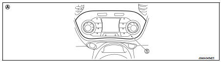
1. Multi display unit
A. With Nissan Dynamic Control system
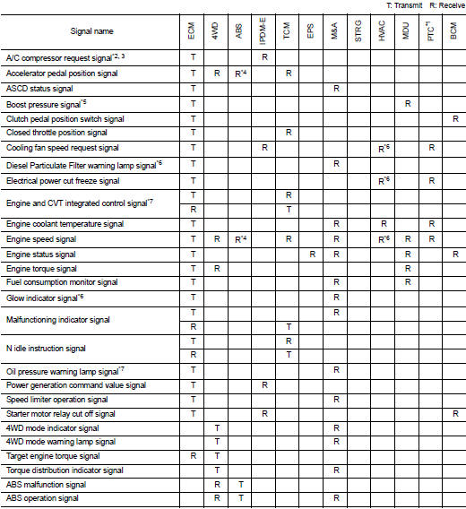
Can communication system : CAN Communication Signal Chart
Refer to LAN-16, "How to Use CAN Communication Signal Chart" for how to use CAN communication signal chart.
NOTE
:
• Refer to LAN-22, "Abbreviation List" for the abbreviations of the connecting
units.
• The air bag diagnosis sensor unit uses CAN communication only for communicating with the diagnostic tool (not with other connected control units).
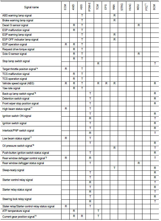
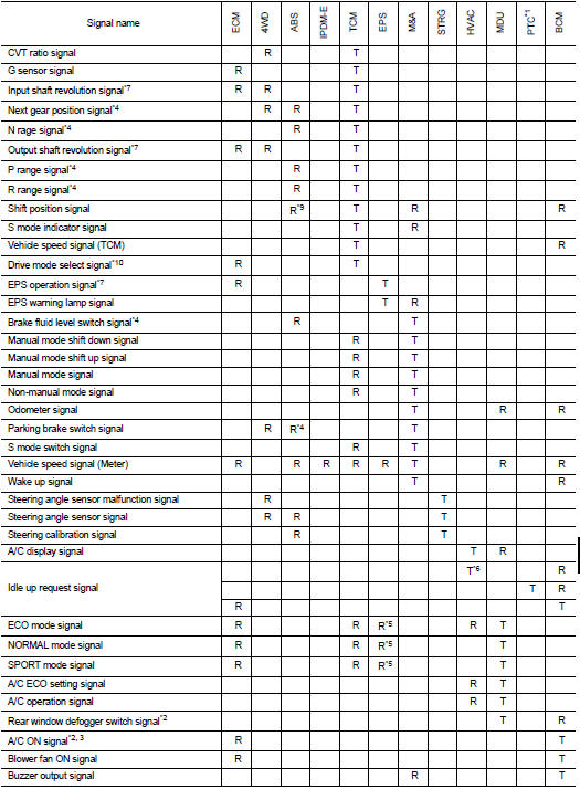
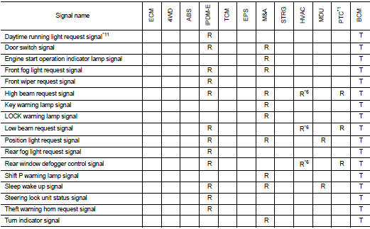
*1: Diesel engine models with manual air conditioning
*2: With automatic air conditioning
*3: With manual air conditioning
*4: Models with ESP
*5: MR16DDT engine models
*6: Diesel engine models
*7: Gasoline engine models
*8: M/T models
*9: CVT models
*10: With Nissan Dynamic Control system
*11: With Daytime running light system
 Component parts
Component Parts Location
LHD MODELS
1. Multi display unit
2. ABS actuator and electric unit (control
unit)
3. A/C auto amp. (With auto air conditioning)
PTC heater control unit (Diesel engine ...
 Wiring diagram
CAN SYSTEM
Wiring Diagram
For connector terminal arrangements, harness layouts, and alphabets in a
(option abbreviation; if not
described in wiring diagram), refer to GI-12, "Connector Infor ...
Other materials:
P1641 thermoplunger control unit
DTC Logic
DTC DETECTION LOGIC
Diagnosis Procedure
1.CHECK THERMOPLUNGER CONTROL UNIT POWER SUPPLY CIRCUIT
1. Turn ignition switch OFF.
2. Disconnect thermoplunger control unit harness connector.
3. Check the voltage between thermoplunger control unit harness connector and
ground.
Is the ...
Can communication circuit
Diagnosis Procedure
1.CONNECTOR INSPECTION
1. Turn the ignition switch OFF.
2. Disconnect the battery cable from the negative terminal.
3. Disconnect all the unit connectors on CAN communication system.
4. Check terminals and connectors for damage, bend and loose connection.
Is the inspectio ...
Differential side oil seal
Exploded View
1. Transaxle assembly
2. Differential side oil seal (left side)
3. Differential side oil seal (right side)
: Always replace after every
disassembly.
: Genuine NISSAN CVT Fluid NS-2
Removal and Installation
REMOVAL
NOTE:
Cap or plug openings to prevent fluid from spilling ...
