Nissan Juke Service and Repair Manual : Water hose
Exploded View
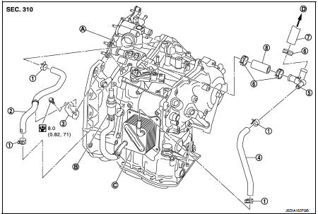
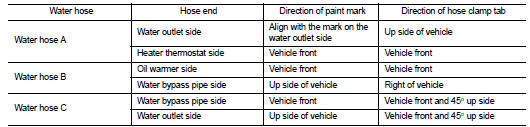
1. Hose clamp
2. Water hose A
3. Water hose B
4. Water hose B
5. Water bypass pipe
6. Hose clamp
7. Heater hose
8. Water hose C
A. Water outlet
B. Heater thermostat
C. Oil warmer
D. Heater core
 : N·m (kg-m, in-lb)
Removal and Installation
REMOVAL
WARNING:
Never remove the radiator cap when the engine is hot. Serious burns could occur
from high pressure
coolant escaping from the radiator.
CAUTION:
Perform these steps after the coolant temperature has cooled sufficiently.
1. Remove the hose clamp and pull out the water hose A.
2. Remove the hose clamp and pull out the water hose B.
3. Remove the hose clamp and pull out the water hose C.
4. Pull out the heater hose and remove the water bypass pipe. Refer to CO-52, "Exploded View".
5. Remove the bracket.
INSTALLATION
Note the following, and install in the reverse order of removal.
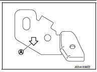
• To install bracket to the CVT assembly, face the from arrow (A) of the bracket ahead of the vehicle.
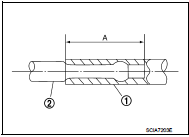
• When installing water hose (1) to tube (2), refer to insertion length “A” below.
Insertion length “A” : 27 mm (1.06 in)
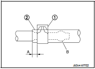
• When hose clamp (1) is installed on CVT water hose (2), refer to dimension “A” below.
Dimension“A” : 5 – 7 mm (0.20 – 0.28 in)
• The hose clamp should not come on bulge (B).
Inspection
INSPECTION AFTER INSTALLATION
Start the engine, and check the joints for coolant leakage.
 Differential side oil seal
Exploded View
1. Transaxle assembly
2. Differential side oil seal (left side)
3. Differential side oil seal (right side)
: Vehicle front
: Always replace after every
disassembly.
: Genuine N ...
 Fluid cooler system
Exploded View
1. Bracket
2. Bracket
3. Bracket
4. CVT fluid cooler
5. Clamp
6. CVT fluid cooler hose C
7. CVT fluid cooler hose B
8. CVT fluid cooler tube assembly
9. CVT fluid cooler ...
Other materials:
Diagnosis and repair work flow
Work Flow
OVERALL SEQUENCE
DETAILED FLOW
1.GET INFORMATION ABOUT SYMPTOM
Get detailed information from the customer about the symptom (the condition
and the environment when the
incident/malfunction occurs).
>> GO TO 2.
2.CHECK DTC
1. Check DTC of “ENGINE”, “BCM” and “IPDM E/R” ...
Unlock sensor
Component Function Check
1.CHECK FUNCTION
1. Select “DOOR LOCK” of “BCM” using CONSULT-III.
2. Select “LOCK STATUS” in “DATA MONITOR” mode.
3. Check that the function operates normally according to the following
conditions.
Is the inspection result normal?
YES >> Unlock sensor is OK. ...
Front power window switch (passenger side)
Component Function Check
1. CHECK FRONT POWER WINDOW SWITCH (PASSENGER SIDE) FUNCTION
Check front power window motor (passenger side) operation with front power
window switch (passenger side).
Is the inspection result normal?
YES >> INSPECTION END
NO >> Refer to PWC-22, "Di ...
