Nissan Juke Service and Repair Manual : U0122 Vehicle dynamics control module
Description
CAN (Controller Area Network) is a serial communication line for real time application. It is an on-vehicle multiplex communication line with high data communication speed and excellent error detection ability. Many electronic control units are equipped onto a vehicle, and each control unit shares information and links with other control units during operation (not independent). In CAN communication, control units are connected with 2 communication lines (CAN H line, CAN L line) allowing a high rate of information transmission with less wiring.
Each control unit transmits/receives data but selectively reads required data only.
DTC Logic
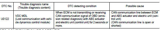
DTC DETECTION LOGIC
DTC CONFIRMATION PROCEDURE
1.PERFORM DTC CONFIRMATION PROCEDURE
1. Turn ignition switch ON and wait at least 3 seconds.
2. Check DTC.
Is DTC detected? YES >> Proceed to EC-160, "Diagnosis Procedure".
NO >> INSPECTION END
Diagnosis Procedure
Perform the trouble diagnosis for CAN communication system. Refer to LAN-17, "Trouble Diagnosis Flow Chart".
 U0101 Can comm circuit
Description
CAN (Controller Area Network) is a serial communication line for real time
application. It is an on-vehicle multiplex
communication line with high data communication speed and excelle ...
 U1001 Can comm circuit
Description
CAN (Controller Area Network) is a serial communication line for real time
application. It is an on-vehicle multiplex
communication line with high data communication speed and excelle ...
Other materials:
On is not displayed when pressing rear window defogger
switch but it is operated
Diagnosis Procedure
1.CHECK MULTI DISPLAY UNIT FUNCTION
Check that the multi display unit is operating normally.
• Auto A/C (4WD models). Refer to HAC-44, "Work Flow".
• Auto A/C (2WD models). Refer to HAC-135, "Work Flow".
Is the inspection result normal?
YES >> ...
Hood switch
Component Function Check
1.CHECK FUNCTION
1. Select “HOOD SW” in “Data Monitor” mode of “IPDM E/R” using CONSULT-III.
2. Check “HOOD SW” indication under the following condition.
Is the indication normal?
YES >> Hood switch is OK.
NO >> Go to SEC-155, "Diagnosis Procedure& ...
Precaution Necessary for Steering Wheel Rotation after Battery Disconnect
NOTE:
• Before removing and installing any control units, first turn the ignition
switch to the LOCK position, then disconnect
both battery cables.
• After finishing work, confirm that all control unit connectors are connected
properly, then re-connect both
battery cables.
• Always use CONS ...
