Nissan Juke Service and Repair Manual : Turbocharger boost control
Turbocharger boost control : SystemDiagram
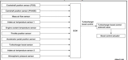
Turbocharger boost control : System Description
INPUT/OUTPUT SIGNAL CHART
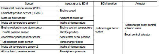
SYSTEM DESCRIPTION
Depending on driving conditions, the ECM performs ON/OFF duty control of the turbocharger boost control solenoid valve and controls the boost by adjusting the pressure to the diaphragm of the boost control actuator.
When driving conditions demand an increase in boost, the ECM prolongs the ON time of the turbocharger boost control solenoid valve and moves the boost control valve towards the closing direction by reducing the pressure in the diaphragm of the boost control actuator. The emission gas to the turbine wheel is then increased. When driving conditions demand a decrease in boost, the ECM shortens the ON time of the turbocharger boost control solenoid valve and moves the boost control valve towards the opening position by increasing the pressure in the diaphragm of the boost control actuator. The emission bypassing to the turbine wheel is then increased. Thus, by performing the most optimal boost control, the ECM improves engine output and response.
NOTE
:
The boost varies depending on the vehicle and driving conditions.
BOOST CONTROL ACTUATOR LINE DRAWING
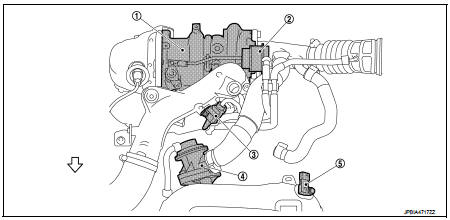
1. Turbocharger
2. Boost control actuator
3. Turbocharger boost control solenoid
valve
4. Recirculation valve
5. Turbocharger boost sensor
(with intake air temperature sensor 2)
 : Vehicle front
 Exhaust valve timing control
Exhaust valve timing control : System Diagram
Exhaust valve timing control: System Description
INPUT/OUTPUT SIGNAL CHART
SYSTEM DESCRIPTION
This mechanism hydraulically controls cam phases c ...
 Engine protection control at low engine oil pressure
Engine protection control at low engine oil pressure : System Diagram
Engine protection control at low engine oil pressure : System Description
INPUT/OUTPUT SIGNAL CHART
SYSTEM DESCRIPTION
• ...
Other materials:
Precaution Necessary for Steering Wheel Rotation after Battery Disconnect
NOTE:
• Before removing and installing any control units, first turn the ignition
switch to the LOCK position, then disconnect
both battery cables.
• After finishing work, confirm that all control unit connectors are connected
properly, then re-connect both
battery cables.
• Always use CONS ...
Precaution for Supplemental Restraint System (SRS) "AIR BAG" and "SEAT BELT
PRE-TENSIONER"
The Supplemental Restraint System such as “AIR BAG” and “SEAT BELT PRE-TENSIONER”,
used along
with a front seat belt, helps to reduce the risk or severity of injury to the
driver and front passenger for certain
types of collision. Information necessary to service the system safely is
include ...
Super lock does not operate
All door
ALL DOOR : Diagnosis Procedure
1.CHECK SUPER LOCK ACTUATOR
Check front driver side super lock actuator.
Refer to DLK-99, "DRIVER SIDE : Component Function Check".
Is the inspection result normal?
YES >> GO TO 2.
NO >> Repair or replace the malfunctioning p ...
