Nissan Juke Service and Repair Manual : System
Charging system
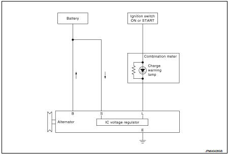
CHARGING SYSTEM : System Diagram
GASOLINE ENGINE MODELS
DIESEL ENGINE MODELS
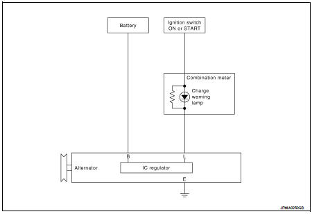
CHARGING SYSTEM : System Description
The alternator provides DC voltage to operate the vehicle's electrical system and to keep the battery charged.
The voltage output is controlled by the IC voltage regulator
Power generation voltage variable control system
POWER GENERATION VOLTAGE VARIABLE CONTROL SYSTEM : System Diagram (Gasoline Engine Models)
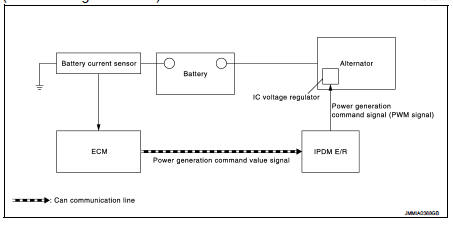
POWER GENERATION VOLTAGE VARIABLE CONTROL SYSTEM : System Description (Gasoline Engine Models)
By performing the power generation voltage variable control, the engine load due to the power generation of the alternator is reduced and fuel consumption is decreased.
NOTE
:
When any malfunction is detected in the power generation voltage variable
control system, the power generation
is performed according to the characteristic of the IC voltage regulator of the
alternator.
 Component parts
Charging system
CHARGING SYSTEM : Component Parts Location
1. Charge warning lamp (On the combination
meter)
2. Alternat
CHARGING SYSTEM : Component Description
Power generation voltage vari ...
 Wiring diagram
CHARGING SYSTEM
Wiring Diagram
GASOLINE ENGINE MODELS
For connector terminal arrangements, harness layouts, and alphabets in a
(option abbreviation; if not
described in wiring diagram), refer to ...
Other materials:
C1607, C1608 EPS control unit
DTC Logic
DTC DETECTION LOGIC
DTC CONFIRMATION PROCEDURE
1.PRECONDITIONING
If “DTC CONFIRMATION PROCEDURE” has been previously conducted, always turn
ignition switch OFF and
wait at least 10 seconds before conducting the next test.
>> GO TO 2.
2.DTC REPRODUCTION PROCEDURE
With ...
P0500 VSS
Description
ECM receives vehicle speed signals from two different paths via CAN
communication line: One is from the
ABS actuator and electric unit (control unit) via the combination unit and the
other is from TCM.
DTC Logic
DTC DETECTION LOGIC
NOTE:
• If DTC P0500 is displayed with DTC UXX ...
B1145 curtain air bag module RH
DTC Logic
DTC DETECTION LOGIC
DTC CONFIRMATION PROCEDURE
1.CHECK SELF-DIAG RESULT
With CONSULT-III
1. Turn ignition switch ON.
2. Perform “Self Diagnostic Result” mode of “AIR BAG” using CONSULT-III.
Without CONSULT-III
1. Turn ignition switch ON.
2. Check the air bag warning lamp statu ...
