Nissan Juke Service and Repair Manual : System
Starting system (with intelligent key) : System Diagram
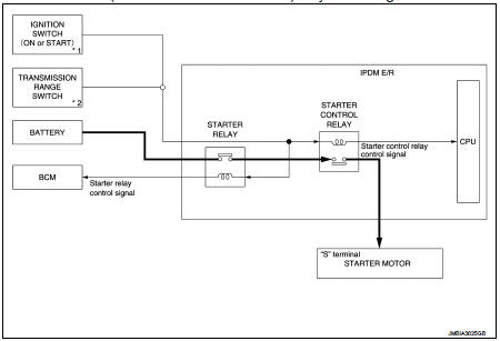
*1: M/T models
*2: CVT models
Starting system (with intelligent key) : System Description
CVT MODELS
• When selector lever is P or N, power is supplied to starter relay and starter control relay by transmission range switch. And BCM and IPDM E/R (CPU) detect selector lever P/N condition by the inputted signal.
• When starter operating condition is satisfied, IPDM E/R turns starter control relay ON by starter control relay control signal.
• When engine cranking condition is satisfied, BCM turns starter relay ON by starter control relay control signal.
• Then battery power is supplied to starter motor (“S” terminal) through starter control relay and starter relay.
M/T MODELS
• When the ignition switch is turned ON or START position power is supplied to starter relay and starter control relay. And BCM and IPDM E/R (CPU) detect ignition switch position by the inputted signal.
• When starter operating condition is satisfied, IPDM E/R turns starter control relay ON by starter control relay control signal.
• When engine cranking condition is satisfied, BCM turns starter relay ON by starter control relay control signal.
• Then battery power is supplied to starter motor (“S” terminal) through starter control relay and starter relay.
Starting system (without intelligent key) : System Diagram
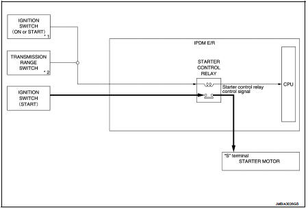
*1: M/T models
*2: CVT model
Starting system (without intelligent key) : System Description
CVT MODELS
• When selector lever is P or N, power is supplied to starter control relay by transmission range switch. And IPDM E/R (CPU) detect selector lever P/N condition by the inputted signal.
• When engine cranking condition is satisfied, then battery power is supplied to starter motor (“S” terminal) through starter control relay.
M/T MODELS
When ignition switch is START position, battery power is supplied to starter motor (“S” terminal).
 Component parts
Starting system (with intelligent key) : Component Parts Location
1. IPDM E/R
Refer to PCS-5, "Component Parts
Location".
2. Transmission range switch (CVT
models)
Refer to TM-131, & ...
 Wiring diagram
...
Other materials:
Precaution Necessary for Steering Wheel Rotation after Battery Disconnect
NOTE:
• Before removing and installing any control units, first turn the ignition
switch to the LOCK position, then disconnect
both battery cables.
• After finishing work, confirm that all control unit connectors are connected
properly, then re-connect both
battery cables.
• Always use CONS ...
P17B7 high clutch solenoid
DTC Logic
DTC DETECTION LOGIC
DTC CONFIRMATION PROCEDURE
1.PREPARATION BEFORE WORK
If another "DTC CONFIRMATION PROCEDURE" occurs just before, turn ignition
switch OFF and wait for at
least 10 seconds, then perform the next test.
>> GO TO 2.
2.CHECK DTC DETECTION
1. S ...
Brake fluid
Inspection
BRAKE FLUID LEVEL
• Check that the fluid level in the reservoir tank is within the specified
range (MAX – MIN lines).
• Visually check for any brake fluid leakage around the reservoir
tank.
• Check the brake system for any leakage if the fluid level is
extremely low (lower than MIN ...
