Nissan Juke Service and Repair Manual : Side oil seal
Exploded View
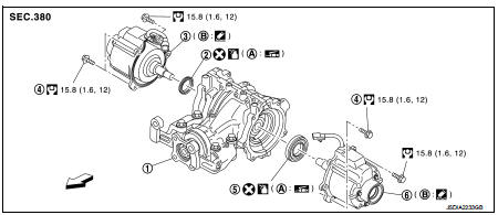
1. Rear final drive assembly
2. Side oil seal (right)
3. Electric controlled coupling (right)
4. Reamer bolt
5. Side oil seal (left)
6. Electric controlled coupling (left)
A. Oil seal lip B. Gear carrier mouting face
 : Vehicle front
 : N·m (kg-m, ft-lb)
 : Always replace after every
disassembly.
 : Apply multi purpose grease
 : Apply gear oil.
 : Apply Genuine Liquid Gasket 1217
or equivalent.
Removal and Installation
REMOVAL
1. Remove electric controlled couplings. Refer to DLN-139, "Removal and Installation".
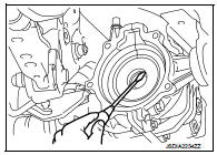
2. Remove side oil seals with a suitable tool.
CAUTION:
Never damage gear carrier and rear cover.
INSTALLATION
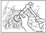
1. Install side oil seal (right side) until it becomes flush with the carrier end, using the drift (A) (SST: KV38100200).
CAUTION:
• Never reuse oil seals.
• When installing, never incline oil seals.
• Apply multi-purpose grease onto oil seal lips, and gear oil onto the circumference of oil seal
.
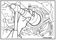
2. Install side oil seal (left side) until it becomes flush with the carrier end, using the drift (A) (SST: KV38100500).
CAUTION:
• Never reuse oil seals.
• When installing, never incline oil seals.
• Apply multi-purpose grease onto oil seal lips, and gear oil onto the circumference of oil seal.
3. Install electric controlled couplings. Refer to DLN-139, "Removal and Installation".
4. When oil leaks while removing, check oil level after the installation.
Refer to DLN-132, "Inspection".
 Front oil seal
Exploded View
1. Rear final drive assembly
2. Front oil seal
3. Companion flange
4. Companion flange lock nut
A. Oil seal lip
: Vehicle front
: N·m (kg-m, ft-lb)
: Never reuse parts
: App ...
 Electric controlled coupling
Exploded View
1. Sub-harness
2. Rear final drive assembly
3. Electric controlled coupling (right)
4. Reamer bolt
5. Electric controlled coupling (left)
A. Gear carrier mouting face
: Vehic ...
Other materials:
B1152 curtain air bag module LH
DTC Logic
DTC DETECTION LOGIC
DTC CONFIRMATION PROCEDURE
1.CHECK SELF-DIAG RESULT
With CONSULT-III
1. Turn ignition switch ON.
2. Perform “Self Diagnostic Result” mode of “AIR BAG” using CONSULT-III.
Without CONSULT-III
1. Turn ignition switch ON.
2. Check the air bag warning lamp statu ...
RearView monitor (if so equipped)
When the shift lever is shifted into the R (Reverse) position, the monitor display
shows the view to the rear of the vehicle.
The system is designed as an aid to the driver in situations such as slot parking
or parallel parking.
WARNING
Failure to follow the warnings and instructions for prop ...
Door switch
Component Function Check
1.CHECK FUNCTION
1. Select “DOOR LOCK” of “BCM” using CONSULT-III.
2. Select “DOOR SW-DR”, “DOOR SW-AS”, “DOOR SW-RL”, “DOOR SW-RR”, “DOOR SW-BK”
in “DATA
MONITOR” mode.
3. Check that the function operates normally according to the following
conditions.
Is the ...
