Nissan Juke Service and Repair Manual : Door switch
Component Function Check
1.CHECK FUNCTION
1. Select “DOOR LOCK” of “BCM” using CONSULT-III.
2. Select “DOOR SW-DR”, “DOOR SW-AS”, “DOOR SW-RL”, “DOOR SW-RR”, “DOOR SW-BK” in “DATA MONITOR” mode.
3. Check that the function operates normally according to the following conditions.
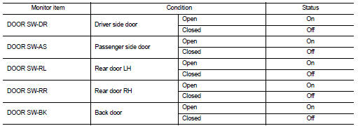
Is the inspection result normal? YES >> Door switch is OK.
NO >> Refer to DLK-87, "Diagnosis Procedure".
Diagnosis Procedure
1.CHECK DOOR SWITCH INPUT SIGNAL
1. Turn ignition switch OFF.
2. Disconnect malfunctioning door switch connector.
3. Check signal between malfunctioning door switch harness connector and ground using oscilloscope.
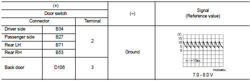
Is the inspection result normal? YES-1 >> Back door: GO TO 3.
YES-2 >> Other door: GO TO 4.
NO >> GO TO 2.
2.CHECK DOOR SWITCH CIRCUIT
1. Disconnect BCM connector.
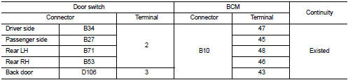
2. Check continuity between door switch harness connector and BCM harness connector.
3. Check continuity between door switch harness connector and ground.
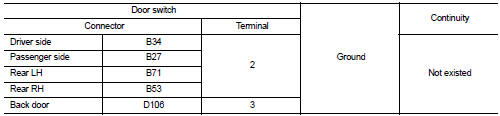
Is the inspection result normal? YES >> Replace BCM. Refer to BCS-93, "Removal and Installation".
NO >> Repair or replace harness.
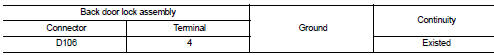
3.CHECK BACK DOOR SWITCH CIRCUIT
Check continuity between back door lock assembly harness connector and ground.
Is the inspection result normal? YES >> GO TO 4.
NO >> Repair or replace harness.
4.CHECK DOOR SWITCH
Refer to DLK-88, "Component Inspection".
Is the inspection result normal? YES >> GO TO 5.
NO >> Replace malfunctioning door switch.
5.CHECK INTERMITTENT INCIDENT
Refer to GI-42, "Intermittent Incident".
>> INSPECTION END
Component Inspection
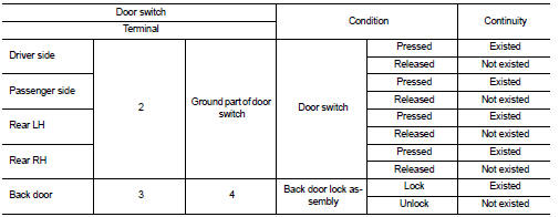
1.CHECK DOOR SWITCH
1. Turn ignition switch OFF.
2. Disconnect malfunctioning door switch connector.
3. Check continuity between door switch terminals.
Is the inspection result normal? YES >> INSPECTION END
NO >> Replace malfunction door switch.
 Door request switch
Component Function Check
1.CHECK FUNCTION
1. Select “INTELLIGENT KEY” of “BCM” using CONSULT-III.
2. Select “REQ SW-DR”, “REQ SW-AS” in “DATA MONITOR” mode.
3. Check that the function operates nor ...
 Hazard function
Component Function Check
1.CHECK FUNCTION
1. Select “INTELLIGENT KEY” of “BCM” using CONSULT-III.
2. Select “FLASHER” in “ACTIVE TEST” mode.
3. Check that the function operates normally according ...
Other materials:
Door does not lock/unlock with intelligent key
Diagnosis Procedure
1.CHECK DTC WITH BCM AND TCM
Check that DTC is not detected with BCM and TCM.
Is the inspection result normal?
YES >> GO TO 2.
NO-1 >> Refer to BCS-67, "DTC Index". (BCM)
NO-2 >> Refer to TM-171, "DTC Index" (RE0F10B models) or TM-3 ...
Trip computer
The switch for the trip computer is located on the meter panel.
When the ignition switch is placed in the ON position, modes of the trip computer
can be selected by pushing the trip computer mode switchA .
Each time the trip computer mode switchA is pushed, the display will change as
follows ...
NISSAN Vehicle Immobilizer System keys
Your vehicle can only be driven with the master keys which are registered to
the NISSAN Vehicle Immobilizer System components in your vehicle. These keys have
a transponder chip in the key head.
Never leave these keys in the vehicle. Additional or replacement keys:
If you still have a key, the ...
