Nissan Juke Service and Repair Manual : Removal and Installation
REMOVAL
1. Separate the rear propeller shaft. Refer to DLN-121, "Removal and Installation".
2. Remove right side drive shaft. Refer to FAX-24, "RIGHT SIDE : Removal and Installation".
3. Remove catalyst convertor support bracket (RH). EM-35, "4WD : Removal and Installation".
4. Remove heat insulator (1).
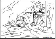
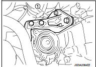
5. Remove transfer gusset (1).
6. Remove catalyst convertor upport bracket rear. EM-59, "4WD : Removal and Installation".
7. Remove rear torque rod and rear torque rod bracket. Refer to EM-59, "4WD : Removal and Installation".
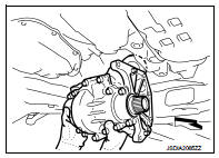
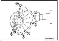
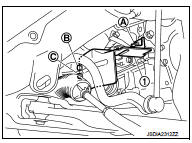
8. Remove the mounting bolts of transaxle assembly and transfer assembly.
9. Remove transfer assembly from the vehicle.
 : Vehicle front
CAUTION:
Never damage ring gear shaft.
INSTALLATION
Note the following, and install in the reverse order of removal.
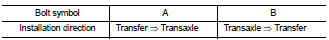
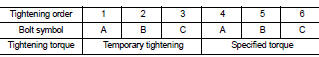
• When installing the transfer to the transaxle, install the mounting bolts following the standard below.
CAUTION:
• When installing transfer assembly to transaxle assembly,
replace the side oil seal (transfer joint). Refer to TM-292,
"Removal and Installation".
• Never damage side oil seal (the joint part of transfer).
• When installing heat insulator (1), install the mounting bolts and nut following procedure.
• Check oil level and check for oil leakage after installation. Refer to DLN-90, "Inspection".
 Exploded View
1. Transfer gusset
2. Transfer assembly
3. Heat insulator
: Vehicle front
: N·m (kg-m, ft-lb)
...

Other materials:
HR16DE : Exploded View
REMOVAL
1. Cylinder block
2. “B” terminal harness
3. “S” terminal harness
4. Starter motor
: Vehicle front
: N·m (kg-m, in-lb)
: N·m (kg-m, ft-lb)
DISASSEMBLY
Type: M000T32172ZE
1. “M” terminal nut
2. Magnetic switch assembly
3. Adjusting plate
4. Metal FR
5. Gear case
6. Yo ...
B2205 vehicle speed
Description
Vehicle speed signal is transmitted from ABS actuator and electric unit
(control unit) via CAN communication
to combination meter.
DTC Logic
DTC DETECTION LOGIC
Diagnosis Procedure
1.PERFORM SELF-DIAGNOSIS OF ABS ACTUATOR AND ELECTRIC UNIT (CONTROL UNIT)
Perform “Self Diagnost ...
Automatic door locks
All doors lock automatically when the vehicle speed reaches 15 MPH (24 km/h).
• All doors unlock automatically when the ignition switch is placed in the OFF
position (models with Intelligent Key system).
• All doors unlock automatically when the key is removed from the ignition
switch (m ...
