Nissan Juke Service and Repair Manual : Rear washer nozzle and tube
Hydraulic Layout
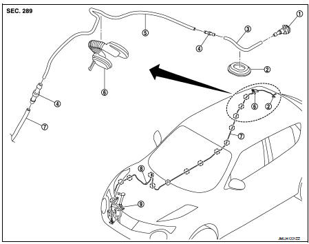
1. Rear washer nozzle
2. Plug
3. Rear washer tube
4. Joint
5. Second washer tube
6. Back door seal rubber
7. Front washer tube
 : Clip
 : Pawl
Removal and Installation
REMOVAL
1. Remove luggage side upper finisher RH. Refer to INT-32, "LUGGAGE SIDE UPPER FINISHER : Removal and Installation".
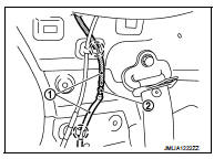
2. Disconnect rear washer tube (2) fixing clip and then remove rear washer tube joint (2) from rear washer tube.
 : Clip
3. Fully open back door.
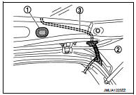
4. Remove back door seal rubber (2), and then remove rear washer tube (3) from back door seal rubber.
5. Remove plug (1).
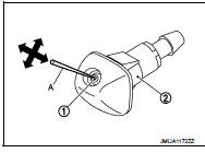
6. Disengage rear washer nozzle (1) fixing pawl with a flat-bladed screwdriver (A) and remove the rear washer nozzle.
CAUTION:
Wrap the flat-bladed screwdriver into a protective tape (B)
to protect the part from damage.
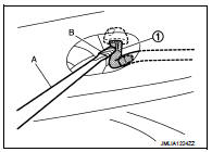
7. Remove rear washer nozzle from the rear washer tube.
INSTALLATION
Install in the reverse order of removal.
Inspection and Adjustment
INSPECTION
Washer Nozzle Inspection Check that air can pass through the hose by blowing forward (toward the nozzle), and check that air cannot pass through by sucking.
ADJUSTMENT
Washer Nozzle Spray Position adjustment Adjust spray positions to match the positions shown in the figure
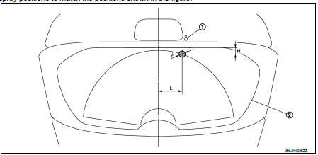
1. Rear washer nozzle 2. Black print frame line

Insert a needle or similar object (A) into the spray opening (1) and move up/down and left/right to adjust the spray position.
NOTE
:
If wax or dust gets into the spray opening of rear washer nozzle (2),
remove wax or dust with a needle or small pin.
 Rear wiper motor
Exploded View
1. Rear wiper motor
2. Rear wiper blade
3. Rear wiper arm
4. Rear wiper arm cover
5. Rear wiper pivot seal
A : Model for cold areas
: Pawl
: N·m (kg-m, in-lb)
: N·m (kg-m, ...
 Defogger
...
Other materials:
ECU diagnosis information
ABS actuator and electric unit (control unit)
Reference Value
CONSULT-III DATA MONITOR STANDARD VALUE
*1: Confirm tire pressure is standard value.
*2: Refer to “valve operation” in BRC-13, "System Description" for valve
operation of each valve.
*3: Refer to BRC-13, "System ...
B1118, B1119 satellite sensor LH
DTC Logic
DTC DETECTION LOGIC
DTC CONFIRMATION PROCEDURE
1.CHECK SELF-DIAG RESULT
With CONSULT-III
1. Turn ignition switch ON.
2. Perform “Self Diagnostic Result” mode of “AIR BAG” using CONSULT-III.
Without CONSULT-III
1. Turn ignition switch ON.
2. Check the air bag warning lamp statu ...
Models without Intelligent Key system
1. Apply the parking brake.
2. Continuously Variable Transmission (CVT) models:
Move the shift lever to the P (Park) or N (Neutral) position. (P is recommended.)
The starter is designed so that it does not operate unless the shift lever is in
either of the above positions.
Manual Transmission ...
