Nissan Juke Service and Repair Manual : ECU diagnosis information
ABS actuator and electric unit (control unit)
Reference Value
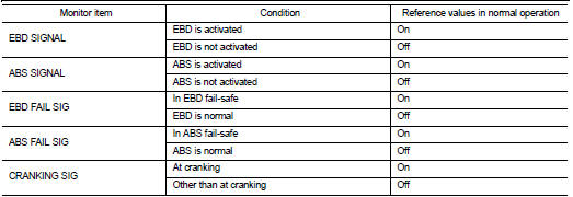
CONSULT-III DATA MONITOR STANDARD VALUE
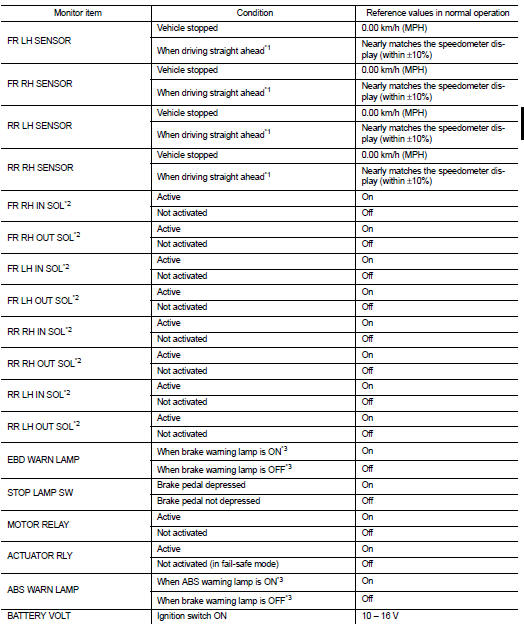
*1: Confirm tire pressure is standard value.
*2: Refer to “valve operation” in BRC-13, "System Description" for valve operation of each valve.
*3: Refer to BRC-13, "System Description" for ON/OFF conditions of each warning lamp and indicator lamp.
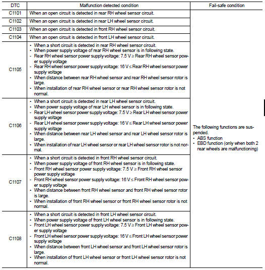
Fail-safe
ABS FUNCTION
ABS warning lamp in combination meter turn ON when a malfunction occurs in system [ABS actuator and electric unit (control unit)]. The control is suspended for ABS function. The vehicle status becomes the same as models without ABS function. However, EBD function is operated normally.
NOTE
:
ABS self-diagnosis sound may be heard the same as in the normal condition,
because self-diagnosis is performed
when ignition switch turns ON and when vehicle initially starts.
EBD FUNCTION
ABS warning lamp and brake warning lamp in combination meter turn ON when a malfunction occurs in system [ABS actuator and electric unit (control unit)]. The control is suspended for ABS function and EBD function.
The vehicle status becomes the same as models without ABS function and EBD function.
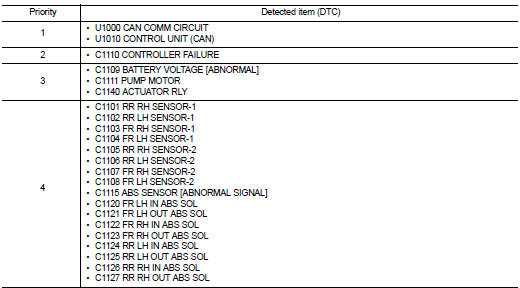
DTC Inspection Priority Chart
When multiple DTCs are displayed simultaneously, check one by one depending on the following priority list.
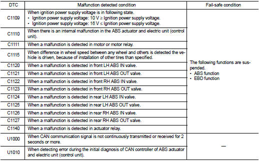
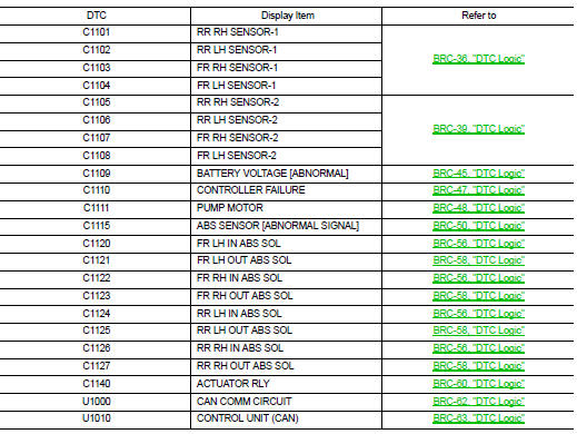
DTC Index
 Diagnosis system [ABS actuator and electric unit (control
unit)]
Diagnosis system [ABS actuator and electric unit (control
unit)]
CONSULT-III Function
APPLICATION ITEMS
CONSULT-III can display each diagnostic item using the diagnostic test modes
as follows.
*: The following diagnosis information is erased by erasing.
• ...
 Wiring diagram
BRAKE CONTROL SYSTEM
Wiring Diagram
For connector terminal arrangements, harness layout, and alphabets in a
(option abbreviation; if not
described in wiring diagram), refer to GI-12, "Connec ...
Other materials:
Precautions for Harness Repair
• Solder the repaired area and wrap tape around the soldered area.
NOTE:
A fray of twisted lines must be within 110 mm (4.33 in).
• Bypass connection is never allowed at the repaired area.
NOTE:
Bypass connection may cause CAN communication error. The
spliced wire becomes separated and t ...
P17B7 high clutch solenoid
DTC Logic
DTC DETECTION LOGIC
DTC CONFIRMATION PROCEDURE
1.PREPARATION BEFORE WORK
If another "DTC CONFIRMATION PROCEDURE" occurs just before, turn ignition
switch OFF and wait for at
least 10 seconds, then perform the next test.
>> GO TO 2.
2.CHECK DTC DETECTION
1. S ...
Component parts
Body control system
BODY CONTROL SYSTEM : Component Parts Location
RHD MODELS
1. BCM
A. Behind of glove box (Left side)
LHD MODELS
1. BCM
A. Behind of instrument lower panel LH
(Left side)
Power consumption control system
POWER CONSUMPTION CONTROL SYSTEM : Component Parts Location
1 ...
