Nissan Juke Service and Repair Manual : P1701 TCM
Description
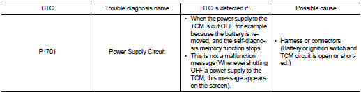
When the power supply to the TCM is cut OFF, for example because the battery is removed, and the self-diagnosis memory function stops, malfunction is detected.
NOTE
:
Since “P1701” will be indicated when replacing TCM, perform diagnosis after
erasing “SELF-DIAG
RESULTS”
DTC Logic
DTC DETECTION LOGIC
DTC CONFIRMATION PROCEDURE
NOTE
:
If “DTC CONFIRMATION PROCEDURE” has been previously conducted, always turn
ignition switch
OFF and wait at least 10 seconds before conducting the next test.
After the repair, perform the following procedure to confirm the malfunction is eliminated.
1.CHECK DTC DETECTION
 With CONSULT-III
1. Turn ignition switch ON.
2. Wait for at least 2 consecutive seconds.
3. Select “Self Diagnostic Results” in “TRANSMISSION”.
Is “P1701” detected? YES >> Go to TM-239, "Diagnosis Procedure".
NO >> Check intermittent incident. Refer to GI-42, "Intermittent Incident".
Diagnosis Procedure
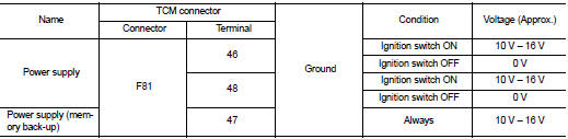
1.CHECK TCM POWER SOURCE
Check voltage between TCM connector terminals and ground.
Is the inspection result normal? YES >> GO TO 4.
NO >> GO TO 2.
2.DETECT MALFUNCTIONING ITEM
Check the following.
• Harness for short or open between battery and TCM connector terminal 47
• Harness for short or open between ignition switch and TCM connector terminal
46, 48
• 10A fuse (No. 55, located in the IPDM E/R)
• 10A fuse (No. 33, located in the J/B)
• Ignition switch. Refer to PG-15, "Wiring Diagram - IGNITION POWER SUPPLY -".
Is the inspection result normal? YES >> GO TO 3.
NO >> Repair or replace damaged parts.
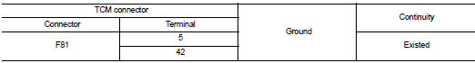
3.CHECK TCM GROUND CIRCUIT
1. Turn ignition switch OFF.
2. Disconnect TCM connector.
3. Check continuity between TCM connector terminals and ground.
Is the inspection result normal? YES >> GO TO 4.
NO >> Repair or replace damaged parts.
4.CHECK TCM
Check TCM input/output signals. Refer to TM-164, "Reference Value".
Is the inspection result normal? YES >> Check intermittent incident. Refer to GI-42, "Intermittent Incident".
NO >> Replace the TCM. Refer to TM-280, "Removal and Installation".
 P1585 G sensor
Description
• G sensor is installed to floor under instrument lower cover.
• G sensor detects longitudinal G and inclination that affects the vehicle and
outputs to ECM using analog voltage.
EC ...
 P1705 TP sensor
Description
Electric throttle control actuator consists of throttle control motor,
accelerator pedal position sensor, throttle
position sensor etc. The actuator sends a signal to the ECM, and ECM ...
Other materials:
P060B ECM
DTC Logic
DTC DETECTION LOGIC
Diagnosis Procedure
1.INSPECTION START
1. Turn ignition switch ON.
2. Erase DTC.
3. Turn ignition switch OFF and wait for 20 seconds.
4. Turn ignition switch ON and perform the self-diagnosis.
Is the DTC P060B displayed again?
YES >> GO TO 2.
NO &g ...
Component parts
INTERIOR LIGHTING SYSTEM
INTERIOR LIGHTING SYSTEM : Component Parts Location
1. IPDM E/R
Refer to PCS-5, "Component Parts
Location"
2. BCM
Refer to BCS-6, "BODY CONTROL
SYSTEM : Component Parts Location"
3. Door lock and unlock switch
4. Front door request switch (driv ...
Intake valve timing control
Intake valve timing control : System Diagram
Intake valve timing control : System Description
INPUT/OUTPUT SIGNAL CHART
SYSTEM DESCRIPTION
This mechanism hydraulically controls cam phases continuously with the fixed
operating angle of the intakevalve.
The ECM receives signals such as ...
