Nissan Juke Service and Repair Manual : P1585 G sensor
Description
• G sensor is installed to floor under instrument lower cover.
• G sensor detects longitudinal G and inclination that affects the vehicle and outputs to ECM using analog voltage.
ECM converts the analog voltage value to digital signal and transmits the signal to TCM via CAN communication.
• TCM detects longitudinal G and inclination of the vehicle using information of CAN communication.
DTC Logic
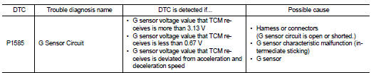
DTC DETECTION LOGIC
DTC CONFIRMATION PROCEDURE
CAUTION:
Always drive vehicle at a safe speed.
1.PRECONDITIONING
Immediately after performing any “DTC CONFIRMATION PROCEDURE”, always turn ignition switch OFF.
Then wait at least 10 seconds before performing the next test.
>> GO TO 2.
2.PERFORM DTC CONFIRMATION PROCEDURE
 With CONSULT-III
1. Start the engine.
2. Select “Data Monitor” in “TRANSMISSION”.
3. Select “VEHICLE SPEED”.
4. Using the “D” position, increase vehicle speed in constant acceleration within 5 seconds.
5. Select “Self Diagnostic Results” in “TRANSMISSION”.
Is “P1585” detected? YES >> Go to TM-236, "Diagnosis Procedure".
NO >> INSPECTION END
Diagnosis Procedure
1.CHECK G SENSOR SIGNAL
 With CONSULT-III
1. Park vehicle on level surface.
2. Turn ignition switch ON.
3. Select “Data Monitor” in “TRANSMISSION”.
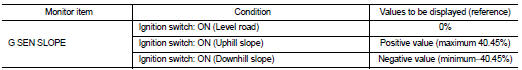
4. Select “G SEN SLOPE”.
5. Check display of “G SEN SLOPE”.
Is the inspection result normal? YES >> GO TO 6.
NO >> GO TO 2.
2.CHECK G SENSOR POWER SOURCE
1. Turn ignition switch OFF.
2. Disconnect G sensor connector.
3. Turn ignition switch ON.
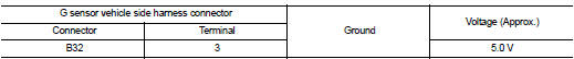
4. Check voltage between G sensor vehicle side harness connector terminal and ground.
Is the inspection result normal? YES >> GO TO 3.
NO >> GO TO 7.
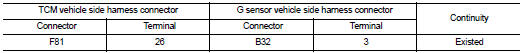
3.CHECK HARNESS BETWEEN TCM AND G SENSOR (PART 1)
1. Turn ignition switch OFF.
2. Disconnect TCM connectors.
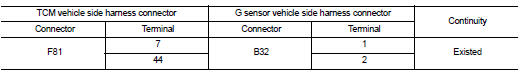
3. Check continuity between TCM vehicle side harness connector terminals and G sensor vehicle side harness connector terminals.
Is the inspection result normal? YES >> GO TO 4.
NO >> Repair or replace damaged parts.
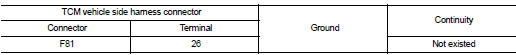
4.CHECK HARNESS BETWEEN TCM AND G SENSOR (PART 2)
Check continuity between TCM vehicle side harness connector terminals and ground.
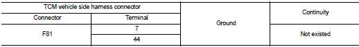
Is the inspection result normal? YES >> GO TO 5.
NO >> Repair or replace damaged parts.
5.CHECK G SENSOR
1. Remove G sensor. Refer to TM-282, "Removal and Installation".
2. Reconnect all the connectors.
3. Turn ignition switch ON.
4. Check voltage between TCM connector terminal and ground.
 : Direction of gravitational
force
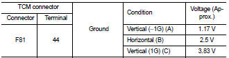
Is the inspection result normal? YES >> GO TO 6.
NO >> Replace G sensor. Refer to TM-282, "Removal and Installation".
6.PERFORM CALIBRATION
1. Install G sensor. Refer to TM-282, "Removal and Installation".
2. Select “Self Diagnostic Results” in “TRANSMISSION”.
3. Select “Erase”.
4. Perform “G SENSOR REMOVAL/INSTALLATION AND REPLACEMENT”. Refer to TM-182, "Description".
Is calibration complete normally? YES >> INSPECTION END
NO >> Check intermittent incident. Refer to GI-42, "Intermittent Incident".
7.CHECK HARNESS BETWEEN TCM AND G SENSOR (SENSOR POWER CIRCUIT) (PART 1)
1. Turn ignition switch OFF.
2. Disconnect TCM connectors.
3. Check continuity between TCM vehicle side harness connector terminal and G sensor vehicle side harness connector terminal.
Is the inspection result normal? YES >> GO TO 8.
NO >> Repair or replace damaged parts.
8.CHECK HARNESS BETWEEN TCM AND G SENSOR (SENSOR POWER CIRCUIT) (PART 2)
Check continuity between TCM vehicle side harness connector terminal and ground.
Is the inspection result normal? YES >> Check intermittent incident. Refer to GI-42, "Intermittent Incident".
NO >> Repair or replace damaged parts.
Special Repair Requirement
1.PERFORM G SENSOR CALIBRATION
Perform “G SENSOR REMOVAL/INSTALLATION AND REPLACEMENT”.
>> Refer to TM-182, "Description".
 P0868 transmission fluid pressure
Description
The secondary pressure solenoid valve regulates the secondary pressure to
suit the driving condition in
response to a signal sent from the TCM.
DTC Logic
DTC DETECTION LOGIC
DTC C ...
 P1701 TCM
Description
When the power supply to the TCM is cut OFF, for example because the battery
is removed, and the self-diagnosis
memory function stops, malfunction is detected.
NOTE:
Since “P1701” ...
Other materials:
P1865 gear ratio signal
DTC Logic
DTC DETECTION LOGIC
DTC CONFIRMATION PROCEDURE
1.PRECONDITIONING
If “DTC CONFIRMATION PROCEDURE” has been previously conducted, always turn
ignition switch OFF and
wait at least 10 seconds before conducting the next test.
>> GO TO 2.
2.DTC REPRODUCTION PROCEDURE
With ...
Inspection
LEVEL
• Check that the reservoir tank engine coolant level is within the
“MIN” to “MAX” when the engine is cool.
A : MAX
B : MIN
• Adjust the engine coolant level if necessary.
LEAKAGE
• To check for leakage, apply pressure to the cooling system with the
radiator cap tester (commercial ser ...
P159B G sensor
For M/T models : DTC Logic
DTC DETECTION LOGIC
DTC CONFIRMATION PROCEDURE
1.PRECONDITIONING
If DTC Confirmation Procedure has been previously conducted, always perform
the following procedure
before conducting the next test.
1. Turn ignition switch OFF and wait at least 10 seconds.
2. T ...
