Nissan Juke Service and Repair Manual : P1078 EVT control position sensor
DTC Logic
DTC DETECTION LOGIC
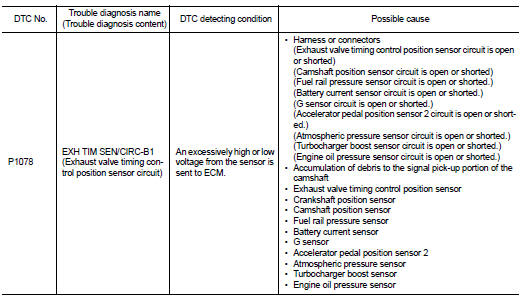
DTC CONFIRMATION PROCEDURE
1.PRECONDITIONING
If DTC Confirmation Procedure has been previously conducted, always perform the following procedure before conducting the next test.
1. Turn ignition switch OFF and wait at least 10 seconds.
2. Turn ignition switch ON.
3. Turn ignition switch OFF and wait at least 10 seconds.
>> GO TO 2.
2.PERFORM DTC CONFIRMATION PROCEDURE
1. Start engine and let it idle for 10 seconds.
2. Check 1st trip DTC.
Is 1st trip DTC detected? YES >> Proceed to EC-313, "Diagnosis Procedure".
NO >> INSPECTION END
Diagnosis Procedure
1.CHECK EXHAUST VALVE TIMING (EVT) CONTROL POSITION SENSOR POWER SUPPLY
1. Turn ignition switch OFF.
2. Disconnect exhaust valve timing (EVT) control position sensor harness connector.
3. Turn ignition switch ON.
4. Check the voltage between EVT control position sensor harness connector and ground.
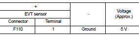
Is the inspection result normal? YES >> GO TO 3.
NO >> GO TO 2.
2.CHECK SENSOR POWER SUPPLY CIRCUIT
1. Turn ignition switch OFF.
2. Disconnect ECM harness connector.
3. Check harness connector for short to power and short to ground, between the following terminals.
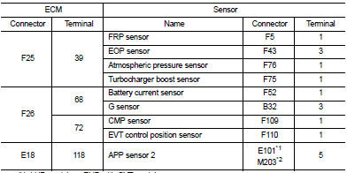
*1: LHD models or RHD with CVT models *2: RHD with M/T models
Is inspection result normal? YES >> Perform the trouble diagnosis for power supply circuit.
NO >> Repair or replace error-detected parts.
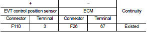
3.CHECK EVT CONTROL POSITION SENSOR GROUND CIRCUIT
1. Turn ignition switch OFF.
2. Disconnect ECM harness connector.
3. Check the continuity between EVT control position sensor harness connector and ECM harness connector.
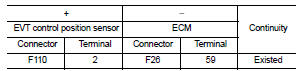
4. Also check harness for short to power.
Is the inspection result normal? YES >> GO TO 4.
NO >> Repair or replace error-detected parts.
4.CHECK EVT CONTROL POSITION SENSOR INPUT SIGNAL CIRCUIT
1. Disconnect ECM harness connector.
2. Check the continuity between EVT control position sensor harness connector and ECM harness connector.
3. Also check harness for short to ground and to power.
Is the inspection result normal? YES >> GO TO 5.
NO >> Repair or replace error-detected parts.
5.CHECK EVT CONTROL POSITION SENSOR
Check the EVT control position sensor. Refer to EC-315, "Component Inspection".
Is the inspection result normal? YES >> GO TO 6.
NO >> Replace EVT control position sensor. Refer to EM-79, "Removal and Installation".
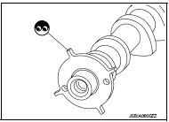
6.CHECK CAMSHAFT (EXT)
Check the following.
• Accumulation of debris to the signal plate of camshaft rear end • Chipping signal plate of camshaft rear end
s the inspection result normal? YES >> Check intermittent incident. Refer to GI-42, "Intermittent Incident".
NO >> Remove debris and clean the signal plate of camshaft rear end or replace camshaft. Refer to EM-79, "Removal and Installation".
Component Inspection
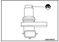
1.EXHAUST VALVE TIMING (EVT) CONTROL POSITION SENSOR-I
1. Turn ignition switch OFF.
2. Disconnect EVT control position sensor harness connector.
3. Loosen the fixing bolt of the sensor.
4. Remove the sensor.
5. Visually check the sensor for chipping.
Is the inspection result normal? YES >> GO TO 2.
NO >> Replace EVT control position sensor. Refer to EM-67, "Exploded View".
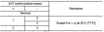
2.EVT CONTROL POSITION SENSOR-II
Check resistance EVT control position sensor terminals as shown below.
Is the inspection result normal? YES >> INSPECTION END
NO >> Replace EVT control position sensor. Refer to EM-67, "Exploded View".
 P0850 PNP switch
Description
For CVT models, transmission range switch is turn ON when the selector lever
is P or N.
For M/T models, park/neutral position (PNP) range switch is ON when the selector
lever is Ne ...
 P1197 out of gas
Description
This diagnosis result is detected when the fuel level of the fuel tank is
extremely low and the engine does not
run normally.
DTC Logic
DTC DETECTION LOGIC
DTC CONFIRMATION PROCED ...
Other materials:
Windshield wiper and washer switch
WARNING
In freezing temperatures the washer solution may freeze on the windshield
and obscure your vision which may lead to an accident. Warm windshield with the
defroster before you wash the windshield.
CAUTION
• Do not operate the washer continuously for more than 30 seconds.
• Do not oper ...
Back door opener switch
Component Function Check
1.CHECK FUNCTION
1. Select “TRUNK” of “BCM” using CONSULT-III.
2. Select “TR/BD OPEN SW” in “DATA MONITOR” mode.
3. Check that the function operates normally according to the following
conditions.
Is the inspection result normal?
YES >> Back door opener switc ...
DTC/circuit diagnosis
Blower motor
Diagnosis Procedure
1.CHECK SYMPTOM
Check symptom (A or B).
Which symptom is detected?
A >> GO TO 2.
B >> GO TO 7.
2.CHECK FUSE
1. Turn ignition switch OFF.
2. Check 15A fuses (Nos. 14 and 16, located in fuse block (J/B)].
NOTE:
Refer to PG-22, "Fuse, ...
