Nissan Juke Service and Repair Manual : P047B exhaust gas pressure sensor 2
DTC Logic
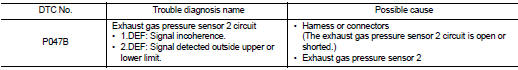
DTC DETECTION LOGIC
Diagnosis Proce
1.CHECK GROUND CONNECTIONS
1. Turn ignition switch OFF and wait at least 20 seconds.
2. Check ground connection E38. Refer to Ground inspection in GI-44, "Circuit Inspection".
Is the inspection result normal? YES >> GO TO 2.
NO >> Repair or replace ground connection.
2.CHECK EXHAUST GAS PRESSURE SENSOR 2 POWER SUPPLY CIRCUIT
1. Disconnect exhaust gas pressure sensor 2 harness connector.
2. Turn ignition switch ON.
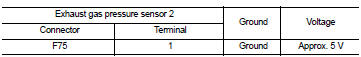
3. Check the voltage between exhaust pressure sensor 2 harness connector and ground.
Is the inspection result normal? YES >> GO TO 3.
NO >> Repair open circuit or short to ground or short to power in harness or connectors.
3.CHECK EXHAUST GAS PRESSURE SENSOR 2 GROUND CIRCUIT FOR OPEN AND SHORT
1. Turn ignition switch OFF and wait at least 20 seconds.
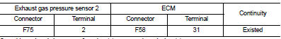
2. Check the continuity between exhaust gas pressure sensor 2 harness connector and ECM harness connector.
3. Also check harness for short to ground and short to power.
Is the inspection result normal? YES >> GO TO 4.
NO >> Repair open circuit or short to ground or short to power in harness or connectors.
4.CHECK EXHAUST GAS PRESSURE SENSOR 2 INPUT SIGNAL CIRCUIT FOR OPEN AND SHORT
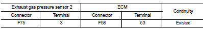
1. Check the continuity between exhaust gas pressure sensor 2 harness connector and ECM harness connector.
2. Also check harness for short to ground and short to power.
Is the inspection result normal? YES >> GO TO 5.
NO >> Repair open circuit or short to ground or short to power in harness or connectors.
5.CHECK INTERMITTENT INCIDENT
Refer to GI-42, "Intermittent Incident".
Is the inspection result normal? YES >> Replace exhaust gas pressure sensor 2.
NO >> Repair or replace.
 P047A exhaust gas pressure sensor 2
DTC Logic
DTC DETECTION LOGIC
NOTE:
If DTC P047A is displayed with DTC P0651, first perform trouble diagnosis for
DTC P0651. Refer to EC-975,
"DTC Logic".
Diagnosis Procedure
1.CHE ...
 P0487 EGR volume control valve
DTC Logic
DTC DETECTION LOGIC
Diagnosis Procedure
1.CHECK EGR VOLUME CONTROL VALVE CONTROL CIRCUIT
1. Turn ignition switch OFF.
2. Disconnect EGR volume control valve harness connector and ECM ...
Other materials:
Power supply and ground circuit
Diagnosis Procedure
1.CHECK GROUND CONNECTION
1. Turn ignition switch OFF.
2. Check ground connection E21 and E38. Refer to Ground Inspection in GI-44,
"Circuit Inspection".
Is the inspection result normal?
YES >> GO TO 2.
NO >> Repair or replace ground connection.
...
Service Notice or Precaution
OBD SELF-DIAGNOSIS (WITH OBD)
• CVT self-diagnosis is performed by the TCM in combination with the ECM. The
results can be read through
the blinking pattern of the malfunction indicator (MI). Refer to the table on
TM-159, "CONSULT-III Function
(TRANSMISSION)" for the indicator used ...
Door cable
Exploded View
LEFT SIDE
1. A/C unit assembly
2. Intake door lever
3. Intake door link
4. Intake door cable
5. Air mix door cable
6. Air mix door link
7. Air mix door rod
8. Lower air mix door lever
9. Upper air mix door lever
10. Max. cool door
A. To A/C control
RIGHT SIDE
...
