Nissan Juke Service and Repair Manual : Door cable
Exploded View
LEFT SIDE
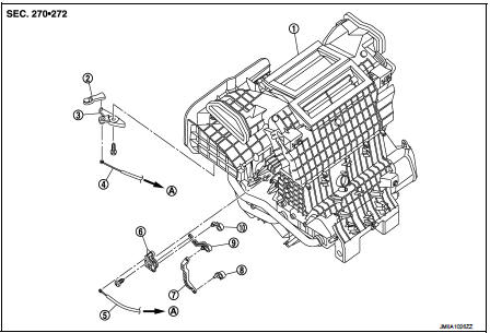
1. A/C unit assembly
2. Intake door lever
3. Intake door link
4. Intake door cable
5. Air mix door cable
6. Air mix door link
7. Air mix door rod
8. Lower air mix door lever
9. Upper air mix door lever
10. Max. cool door
A. To A/C control
RIGHT SIDE
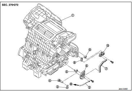
1. A/C unit assembly
2. Mode door cable
3. Foot door lever
4. Foot door link
5. Side ventilator door lever
6. Mode door main link
7. Mode door main link adapter rod
8. Center ventilator door lever
9. Defroster door lever
10. Mode door main link adapter
A. To A/C control
Intake door cable : Removal and Installation
REMOVAL
1. Disconnect intake door cable from A/C control. Refer to HAC-308, "Exploded View".
2. Remove instrument lower panel LH. Refer to IP-13, "Removal and Installation".
(LHD models)
3. Remove glove box assembly. Refer to IP-13, "Removal and Installation". (RHD
models)
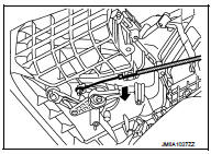
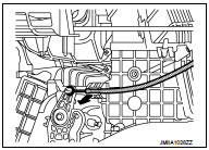
4. Disconnect intake door cable from A/C unit assembly as shown
by the arrow in the figure, and then remove intake door cable.
INSTALLATION
Install in the reverse order of removal.
Mode door cable : Removal and Installation
REMOVAL
1. Disconnect mode door cable from A/C control. Refer to HAC-308, "Exploded View".
2. Remove glove box assembly. Refer to IP-13, "Removal and Installation". (LHD
models)
3. Remove instrument panel RH. Refer to IP-13, "Removal and Installation". (RHD
models)
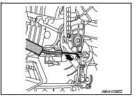
4. Disconnect mode door cable from A/C unit assembly as shown
by the arrow in the figure, and then remove mode door cable.
INSTALLATION
Install in the reverse order of removal.
Air mix door cable : Removal and Installation
REMOVAL
1. Disconnect air mix door cable from A/C control. Refer to HAC-308, "Exploded View".
2. Remove instrument panel LH. Refer to IP-13, "Removal and Installation". (LHD
models)
3. Remove glove box assembly. Refer to IP-13, "Removal and Installation". (RHD
models)
4. Disconnect air mix door cable from A/C unit assembly as shown
by the arrow in the figure, and then remove air mix door cable.
INSTALLATION
Install in the reverse order of removal.
 Blower fan resistor
Exploded View
1. A/C unit assembly
2. Fan control amp.*1
3. Blower fan resistor*2
4. Blower motor
5. Blower motor cover
• *1: Automatic air conditioner
• *2: Manual air conditioner
Remov ...

Other materials:
P0725 engine speed
Description
The engine speed signal is transmitted from ECM to TCM by CAN communication
line.
DTC Logic
DTC DETECTION LOGI
DTC CONFIRMATION PROCEDURE
CAUTION:
Always drive vehicle at a safe speed.
NOTE:
If “DTC CONFIRMATION PROCEDURE” has been previously performed, always turn
ignition ...
Can communication circuit
Diagnosis Procedure
1.CONNECTOR INSPECTION
1. Turn the ignition switch OFF.
2. Disconnect the battery cable from the negative terminal.
3. Disconnect all the unit connectors on CAN communication system.
4. Check terminals and connectors for damage, bend and loose connection.
Is the inspectio ...
Back door does not opened
Diagnosis Procedure
1.CHECK BACK DOOR OPENER SWITCH
Check back door opener switch.
Refer to DLK-513, "Component Function Check".
Is the inspection result normal?
YES >> GO TO 2.
NO >> Repair or replace the malfunctioning parts.
2.CHECK BACK DOOR OPENER ACTUATOR
...
