Nissan Juke Service and Repair Manual : P012B TC boost sensor
DTC Logic
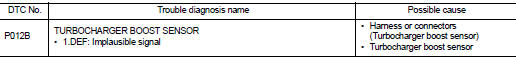
DTC DETECTION LOGIC
Diagnosis Procedure
1.CHECK GROUND CONNECTIONS
1. Turn ignition switch OFF.
2. Check ground connection E38. Refer to Ground inspection in GI-44, "Circuit Inspection".
Is the inspection result normal? YES >> GO TO 2.
NO >> Repair or replace ground connection.
2.CHECK TUBOCHARGER BOOST SENSOR SUPPLY CIRCUIT
1. Disconnect turbocharger boost sensor harness connector.
2. Turn ignition switch ON.
3. Check the voltage between turbocharger boost sensor connector and ground.
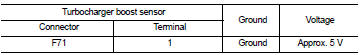
Is the inspection result normal? YES >> GO TO 3.
NO >> Repair open circuit or short to ground or short to power in harness or connectors.
3.CHECK TUBOCHARGER BOOST SENSOR GROUND CIRCUIT FOR OPEN AND
SHORT
1. Turn ignition switch OFF.
2. Disconnect ECM harness connector.
3. Check the continuity between turbocharger boost sensor harness connector and ECM harness connector.
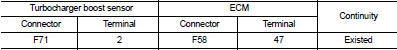
4. Also check harness for short to ground and short to power.
Is the inspection result normal? YES >> GO TO 4.
NO >> Repair open circuit or short to ground or short to power in harness or connectors.
4.CHECK TUBOCHARGER BOOST SENSOR INPUT SIGNAL CIRCUIT FOR OPEN AND SHORT
1. Check the continuity between turbocharger boost sensor harness connector and ECM harness connector.
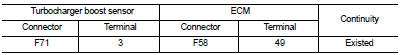
2. Also check harness for short to ground and short to power.
Is the inspection result normal?
YES >> GO TO 5.
NO >> Repair open circuit or short to ground or short to power in harness or connectors.
5.CHECK TUBOCHARGER BOOST SENSOR
Refer to EC-914, "Component Inspection".
Is the inspection result normal? YES >> GO TO 6.
NO >> Replace turbocharger boost sensor.
6.REPLACE ECM
1. Perform EC-879, "Work Procedure".
2. Perform EGR volume control valve closed position learning. Refer to EC-881, "Work Procedure".
>> INSPECTION END
Component Inspection
1.CHECK TURBOCHARGER BOOST SENSOR-I
1. Turn ignition switch OFF.
2. Remove turbocharger boost sensor with its harness connected.
3. Turn ignition switch ON.
4. Select ???DATA MONITOR??? mode with CONSULT-III.
5. Check ???BOOST PRESS??? and ???ATOMOS PRESS??? indication.
If the value is not very close to ???ATOMOS PRESS???, maximum pressure difference between ???ATOMOS PRESS??? and ???BOOST PRESS??? with the ignition switch ON (engine stop) = ?± 50 mbar? YES >> GO TO 2.
NO >> Replace turbocharger boost sensor.
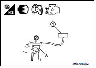
2.CHECK TURBOCHARGER BOOST SENSOR-II
1. Use pump (A) to apply turbocharger boost sensor (1) as shown in the figure.
2. Apply a pressure of between 10 kPa (0.100 bar, 0.102 kg/cm2, 1.5 psi) - 13 kPa (0.130 bar, 0.133 kg/cm2, 1.9 psi) [maximum pressure to be applied: 13 kPa (0.130 bar, 0.133 kg/cm2, 1.9 psi)].
3. Select ???DATA MONITOR??? mode with CONSULT-III.
4. Check ???BOOST PRESS??? indication with that given by the vacuum pump.
If there is no discrepancy? YES >> INSPECTION END
NO >> Replace turbocharger boost sensor.
 P012A TC boost sensor
DTC Logic
DTC DETECTION LOGIC
Diagnosis Procedure
1.CHECK GROUND CONNECTIONS
1. Turn ignition switch OFF.
2. Check ground connection E38. Refer to Ground inspection in GI-44, "Circuit
In ...
 P0180 FPT sensor
DTC Logic
DTC DETECTION LOGIC
Diagnosis Procedure
1.CHECK GROUND CONNECTIONS
1. Turn ignition switch OFF.
2. Check ground connection E38. Refer to Ground inspection in GI-44, "Circuit
In ...
Other materials:
U1010 control unit (CAN)
Description
CAN (Controller Area Network) is a serial communication line for real time
application. It is an on-vehicle multiplex
communication line with high data communication speed and excellent malfunction
detection ability.
Many electronic control units are equipped onto a vehicle, and ...
Component parts
Component Parts Location
1. Parking brake switch
2. Seat belt buckle switch (passenger
side)
3. Occupant detection unit
(Under the passenger seat cushion
pad)
4. ABS actuator and electric unit (control
unit)
Refer to BRC-97, "Component Parts
Location" (with ESP).
Refer to B ...
Transfer case
Exploded View
1. Pinion lock nut
2. Companion flange
3. Drive pion oil seal
4. Pinon rear bearing
5. Transfer case
6. Gasket
7. Filler plug
8. Collapsible spacer
9. Drive pinion adjust shim
10. Drive pinion
11. Pinion front bearing
12. Ring gear
13. Ring gear shaft
14. Ring ...
