Nissan Juke Service and Repair Manual : P0090 fuel pump
DTC Logic
DTC DETECTION LOGIC
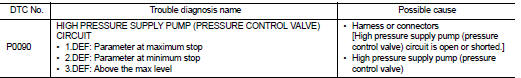
Diagnosis Procedure
1.CHECK HIGH PRESSURE SUPPLY PUMP (PRESSURE CONTROL VALVE) POWER SUPPLY
1. Turn ignition switch OFF.
2. Disconnect high pressure supply pump (pressure control valve) harness connector.
3. Turn ignition switch ON.
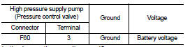
4. Check the voltage between high pressure supply pump (pressure control valve) harness connector and ground.
Is the inspection result normal? YES >> GO TO 3.
NO >> GO TO 2.
2.DETECT MALFUNCTIONING PART
Check the following.
• Harness or connectors E8, F1 • Harness for open or short between IPDM E/R and high pressure supply pump (pressure control valve)
>> Repair open circuit or short to ground or short to power in harness or connectors.
3.CHECK HIGH PRESSURE SUPPLY PUMP (PRESSURE CONTROL VALVE) OUTPUT SIGNAL CIRCUIT FOR OPEN AND SHORT
1. Turn ignition switch OFF.
2. Disconnect ECM harness connector.
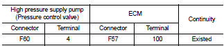
3. Check the continuity between high pressure supply pump (pressure control valve) harness connector and ECM harness connector.
4. Also check harness for short to ground and short to power.
Is the inspection result normal? YES >> GO TO 4.
NO >> Repair open circuit or short to ground or short to power in harness or connectors.
4.HIGH PRESSURE SUPPLY PUMP (PRESSURE CONTROL VALVE) CHECK
Refer to EC-900, "Component Inspection".
Is the inspection result normal? Yes >> GO TO 5.
No >> Replace high pressure supply pump.
5.CHECK INTERMITTENT INCIDENT
Refer to GI-42, "Intermittent Incident", ???INCIDENT SIMULATION TESTS??? and ???GROUND INSPECTION???.
>> INSPECTIO END
Component Inspection
1.CHECK HIGH PRESSURE SUPPLY PUMP (PRESSURE CONTROL VALVE)
1. Turn ignition switch OFF.
2. Disconnect high pressure supply pump (pressure control valve) harness connector.
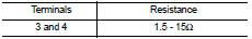
3. Check resistance between high pressure supply pump (pressure control valve) terminals as follows.
the inspection result normal? YES >> INSPECTION END
NO >> Replace high pressure supply pump.
 P0089 fuel pump
DTC Logic
DTC DETECTION LOGIC
NOTE:
• Conditions for applying the diagnostic procedure to the stored DTCs:
The DTC becomes present during the first 30 seconds after the engine starts.
• In low ...
 P0100 MAF sensor
DTC Logic
DTC DETECTION LOGIC
Diagnosis Procedure
1.CHECK GROUND CONNECTIONS
1. Turn ignition switch OFF.
2. Check ground connection E38. Refer to Ground inspection in GI-44, "Circuit
In ...
Other materials:
Exhaust valve timing control
Exhaust valve timing control : System Diagram
Exhaust valve timing control: System Description
INPUT/OUTPUT SIGNAL CHART
SYSTEM DESCRIPTION
This mechanism hydraulically controls cam phases continuously with the fixed
operating angle of the exhaust
valve.
The ECM receives signals such ...
Off position warning does not operate
Diagnosis Procedure
1.CHECK DTC WITH BCM AND COMBINATION METER
Check that DTC is not detected with BCM and combination meter.
Is the inspection result normal?
YES >> GO TO 2.
NO-1 >> Refer to BCS-67, "DTC Index". (BCM)
NO-2 >> Refer to MWI-36, "DTC Index&qu ...
B26F8 BCM
DTC Logic
DTC DETECTION LOGIC
NOTE:
DTC B26F8 can be detected even though the related circuit is not used in this
vehicle.
DTC CONFIRMATION PROCEDURE
1.PERFORM DTC CONFIRMATION PROCEDURE
1. Turn ignition switch ON and wait 1 second.
2. Check DTC in “Self Diagnostic Result” mode of “BCM” u ...
