Nissan Juke Owners Manual : Map light control switch (if so equipped)
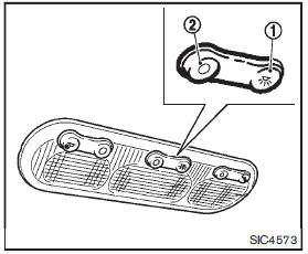
The map lights control switch has three positions: ON1 , OFF2 and center.
ON position
When the switch is in the ON position 1 , the map lights will illuminate.
OFF position
When the switch is in the OFF position2 , the map lights will not illuminate, regardless of the condition.
Center position
When the switch is in the center position, the map lights will illuminate under the following conditions:
• ignition switch is placed in the OFF position (models with Intelligent
Key system)
— remain on for about 15 seconds.
• the key is removed from the ignition switch (models without Intelligent Key system) — remain on for about 15 seconds.
• doors are unlocked by pushing the UNLOCK button (on the keyfob or Intelligent Key) or the request switch (Intelligent Key system equipped model), with the ignition switch in the LOCK position — remain on for about 15 seconds.
• any door is opened and then closed with the ignition switch in the LOCK
position
— remain on for about 15 seconds.
• any door is opened with the ignition switch in the ACC or ON position — remain on while the door is opened.
When the door is closed, the lights go off.
The lights will turn off after a period of time when the lights remain illuminated to prevent the battery from becoming discharged.
 Map lights (if so equipped)
Operate the map light switch to turn the map light on or off.
1 : ON position
2 : OFF position ...
 Cargo light
The cargo room lights illuminate when the lift gate is opened. When the lift
gate is closed, the lights will turn off. ...
Other materials:
Precaution for Supplemental Restraint System (SRS) "AIR BAG" and "SEAT BELT
PRE-TENSIONER"
The Supplemental Restraint System such as “AIR BAG” and “SEAT BELT PRE-TENSIONER”,
used along
with a front seat belt, helps to reduce the risk or severity of injury to the
driver and front passenger for certain
types of collision. Information necessary to service the system safely is
include ...
Compressor
Exploded View
REMOVAL
1. High-pressure flexible hose
2. O-ring
3. Compressor
4. O-ring
5. Low-pressure flexible hose
A. To condenser
B. To evaporator
: N·m (kg-m, ft-lb)
DISASSEMBLY
1. Compressor unit
2. Field coil
3. Snap ring
4. Pulley assembly
5. Snap ring
6. Shim
7. ...
Test Value and Test Limit
The following is the information specified in Service $06 of ISO 15031-5.
The test value is a parameter used to determine whether a system/circuit
diagnostic test is OK or NG while
being monitored by the ECM during self-diagnosis. The test limit is a reference
value which is specified as the ...
