Nissan Juke Service and Repair Manual : IPDM-E branch line circuit
Diagnosis Procedure
1.CHECK CONNECTOR
1. Turn the ignition switch OFF.
2. Disconnect the battery cable from the negative terminal.
3. Check the terminals and connectors of the IPDM E/R for damage, bend and loose connection (unit side and connector side).
Is the inspection result normal? YES >> GO TO 2.
NO >> Repair the terminal and connector.
2.CHECK HARNESS FOR OPEN CIRCUIT
1. Disconnect the connector of IPDM E/R.
2. Check the resistance between the IPDM E/R harness connector terminals.
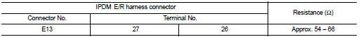
Is the measurement value within the specification? YES >> GO TO 3.
NO >> Repair the IPDM E/R branch line.
3.CHECK POWER SUPPLY AND GROUND CIRCUIT
Check the power supply and the ground circuit of the IPDM E/R. Refer to the following.
• Models with Intelligent Key system: PCS-33, "Diagnosis Procedure" • Models without Intelligent Key system: PCS-62, "Diagnosis Procedure"
Is the inspection result normal? YES (Present error)>>Replace the IPDM E/R. Refer to the following.
• Models with Intelligent Key system: PCS-34, "Removal and Installation" • Models without Intelligent Key system: PCS-63, "Removal and Installation"
YES (Past error)>>Error was detected in the IPDM E/R branch line.
NO >> Repair the power supply and the ground circuit.
 ABS branch line circuit
Diagnosis Procedure
1.CHECK CONNECTOR
1. Turn the ignition switch OFF.
2. Disconnect the battery cable from the negative terminal.
3. Check the terminals and connectors of the ABS actuator and ele ...
 TCM branch line circuit
Diagnosis Procedure
1.CHECK CONNECTOR
1. Turn the ignition switch OFF.
2. Disconnect the battery cable from the negative terminal.
3. Check the following terminals and connectors for damage, bend ...
Other materials:
Component parts
Component Parts Location
1. Hazard switch
2. Parking lamp
3. Front turn signal lamp
4. Front fog lamp*1
5. Headlamp
6. ECM
Refer to EC-461, "ECM".
7. IPDM E/R
Refer to PCS-5, "Component Parts
Location".
8. BCM
Refer to BCS-6, "BODY CONTROL
SYSTEM : Compone ...
Additional service when replacing transaxle assembly
Description
Perform the following work after the transaxle assembly is replaced.
CHECK LOADING OF CALIBRATION DATA
• The TCM acquires calibration data (individual characteristic value) of each
solenoid that is stored in the
ROM assembly (in the control valve). This enables the TCM to perform ...
Precaution
Precaution for Supplemental Restraint System (SRS) "AIR BAG" and "SEAT
BELT
PRE-TENSIONER"
The Supplemental Restraint System such as “AIR BAG” and “SEAT BELT
PRE-TENSIONER”, used along
with a front seat belt, helps to reduce the risk or severity of injury to the
driver a ...
