Nissan Juke Service and Repair Manual : Headlamp washer circuit
Component Function Check
1.CHECK HEADLAMP WASHER OPERATION
 CONSULT-III ACTIVE TEST
1. Select “HEAD LAMP WASHER” of IPDM E/R active test item.
2. With operating the test item, check headlamp operation.
On :Headlamp washer ON operation Off :Stop the headlamp washer.
Is headlamp washer operation normally? YES >> Headlamp washer circuit is normal.
NO >> Refer to WW-50, "Diagnosis Procedure".
Diagnosis Procedure
1.CHECK HEADLAMP WASHER FUSIBLE LINK
1. Turn the ignition switch OFF.
2. Check that the headlamp washer 30A fusible link (#L) is not fusing.
Is the fusible link fusing? YES >> Replace the fusible link after repairing the applicable circuit.
NO >> GO TO 2.
2.CHECK HEADLAMP WASHER RELAY POWER SUPPLY
1. Remove headlamp washer relay.
2. Check voltage between headlamp washer relay harness connector and ground.
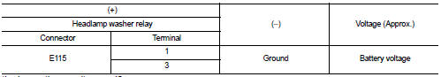
Is the inspection result normal? YES >> GO TO 3.
NO >> Repair harnesses or connectors.
3.CHECK HEADLAMP WASHER RELAY
Check headlamp washer relay. Refer to WW-49, "Component Inspection".
Is the headlamp washer relay normal? YES >> GO TO 4.
NO >> Replace headlamp washer relay.
4.CHECK HEADLAMP WASHER RELAY CONTROL SIGNAL
 CONSULT-III ACTIVE TEST
1. Turn the ignition switch OFF.
2. Install headlamp washer relay.
3. Turn the ignition switch ON.
4. Select “HEAD LAMP WASHER” of IPDM E/R active test item.
5. With operating the test item, check voltage between IPDM E/R harness connector and ground.
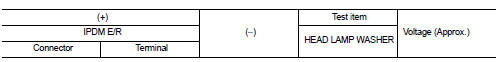

Is the inspection result normal? YES >> GO TO 7.
Fixed at 0 V >> GO TO 5.
Fixed at battery voltage >>Replace IPDM E/R.
5.CHECK HEADLAMP WASHER RELAY CONTROL SIGNAL OPEN CIRCUIT
1. Turn the ignition switch OFF.
2. Remove headlamp washer relay.
3. Disconnect IPDM E/R harness connector.
4. Check continuity between IPDM E/R harness connector and headlamp washer relay harness connector.
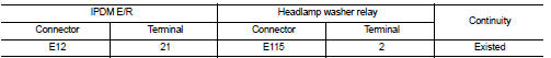
Is the inspection result normal? YES >> GO TO 6.
NO >> Repair the harnesses or connectors.
6.CHECK HEADLAMP WASHER RELAY CONTROL SIGNAL SHORT CIRCUIT
Check continuity between IPDM E/R harness connector and ground.
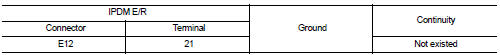
Is the inspection result normal? YES >> Repair the harnesses or connectors.
NO >> Replace IPDM E/R.
7.CHECK HEADLAMP WASHER PUMP OPEN CIRCUIT
1. Turn the ignition switch OFF.
2. Remove headlamp washer relay.
3. Disconnect headlamp washer pump connector.
4. Check continuity between headlamp washer relay harness connector and headlamp washer pump harness connector.
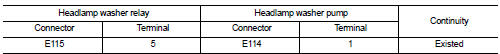
Is the inspection result normal? YES >> GO TO 8.
NO >> Repair the harnesses or connectors.
8.CHECK HEADLAMP WASHER PUMP (GND) OPEN CIRCUIT
Check continuity headlamp washer pump harness connector and ground.
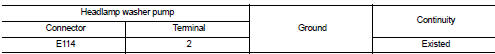
Is the inspection result normal? YES >> Replace headlamp washer pump.
NO >> Repair the harnesses or connectors.
 Headlamp washer relay
Component Inspection
1.CHECK HEADLAMP WASHER RELAY
1. Turn the ignition switch OFF.
2. Remove headlamp washer relay.
3. Apply battery voltage to headlamp washer relay between terminals 1 and 2.
4 ...
 Wiper and washer system
Wiring Diagram - WIPER AND WASHER SYSTEM -
For connector terminal arrangements, harness layouts, and alphabets in a
(option abbreviation; if not
described in wiring diagram), refer to GI-12, " ...
Other materials:
P2127, P2128 APP sensor
DTC Logic
DTC DETECTION LOGIC
DTC CONFIRMATION PROCEDURE
1.PRECONDITIONING
If DTC Confirmation Procedure has been previously conducted, always turn
ignition switch OFF and wait at
least 10 seconds before conducting the next test.
TESTING CONDITION:
Before performing the following proced ...
U1000 can comm circuit
Description
CAN (Controller Area Network) is a serial communication system for real time
application. It is an on-vehicle
multiplex communication system with high data communication speed and excellent
error detection ability.
Many electronic control units are equipped onto vehicles, and ea ...
Additional service when removing battery negative terminal
Description
• The audio unit is equipped with the anti-theft system.
• The audio unit operates after authenticating a fixed four-digit anti-theft
code.
• After removing the battery of the audio unit, the authentication of the
anti-theft code is required.
Work Procedure
1.POWER SWITCH ON
1. ...
